11 sealing arrangements – Flowserve CPXM User Manual
Page 22
CPXM and CPXRM USER INSTRUCTIONS ENGLISH 71569101 10-08
Page 22 of 32
flowserve.com
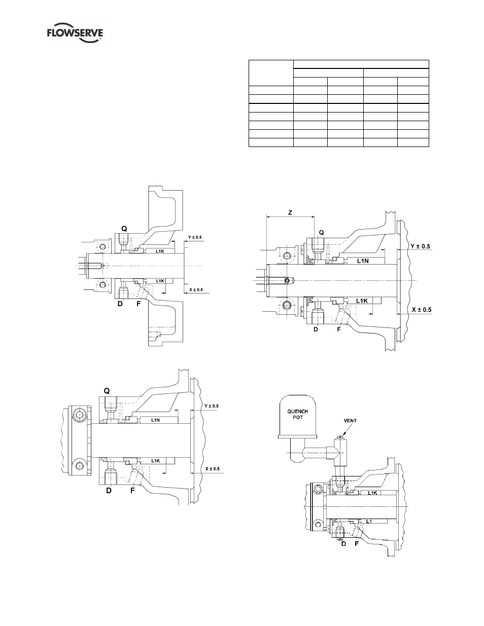
6.11 Sealing arrangements
The following section shows details of the seal
arrangements. The dimensions provided are for non-
step balanced mechanical seals conforming to
EN 12757 L1K and L1N. Contact your nearest
Flowserve sales office or service centre if you require
further information, such as a mechanical seal
dimensional drawing, or are unsure of the specific
arrangement supplied. Refer also to section 4.5.5,
Auxiliary piping.
6.11.1 Single seal types
6.11.1a Single seal
Q - Rp ¼ in. quench
D - Rp ¼ in. drain
F - Rp ¼ in. flush
6.11.1b Single seal with external neck bush
Q - Rp ¼ in. quench
D - Rp ¼ in. drain
F - Rp ¼ in. flush
6.11.1c Single seal variants
1) Self setting collar.
2) Separate seal drive collar set to dimension 'X'.
3) Integral seal drive collar with screws set to
dimension 'X'.
L1K and L1N are seal lengths defined within seal
standard EN 12757.
Setting dimension (mm)
Stubshaft Ø 35
Stubshaft Ø 45
Pump size
X
Y
X
Y
125
25.5
13
-
-
160
25.5
13
36
21
65-160
25.5
13
36
21
100-160
25.5
13
36
21
200
25.5
13
36
21
250
-
-
36
21
315
-
-
36
21
6.11.2 Single seal types with external lip seal
6.11.2a Single seal with external lip seal
Hard sleeve setting dimension 'z' = distance from
stubshaft end to position of sleeve as shown
Q - Rp ¼ in. quench
D - Rp ¼ in. drain
F - Rp ¼ in. flush
6.11.2b Single seal with external lip seal and
quench pot
F - Rp ¼ in. flush
D - Rp ¼ in. drain