3 spare parts, 4 recommended spares, 5 tools required – Flowserve CPXM User Manual
Page 18
CPXM and CPXRM USER INSTRUCTIONS ENGLISH 71569101 10-08
Page 18 of 32
flowserve.com
c) Check that shaft seal leaks are within acceptable
limits.
d) Check any auxiliary supplies eg heating/cooling
(if fitted) are functioning correctly.
Refer to the manuals of any associated
equipment for routine checks needed.
6.2.2 Periodic inspection (six monthly)
a)
Check foundation bolts for
security of attachment and corrosion.
b)
Refer to the manuals of any associated
equipment for periodic checks needed.
6.2.3 Mechanical seals
When leakage becomes unacceptable the seal will
need replacement.
6.3 Spare parts
6.3.1 Ordering of spares
Flowserve keeps records of all pumps that have been
supplied. When ordering spares the following
information should be quoted.
1)
Pump serial number.
2)
Pump size.
3)
Part name – taken from section 8.
4)
Part number – taken from section 8.
5)
Number of parts required.
The pump size and serial number are shown on the
pump nameplate.
To ensure continued satisfactory operation, replacement
parts to the original design specification should be
obtained from Flowserve. Any change to the original
design specification (modification or use of a non-
standard part) will invalidate the pump’s safety
certification.
6.3.2 Storage of spares
Spares should be stored in a clean dry area away
from vibration. Inspection and re-treatment of
metallic surfaces (if necessary) with preservative is
recommended at 6 monthly intervals.
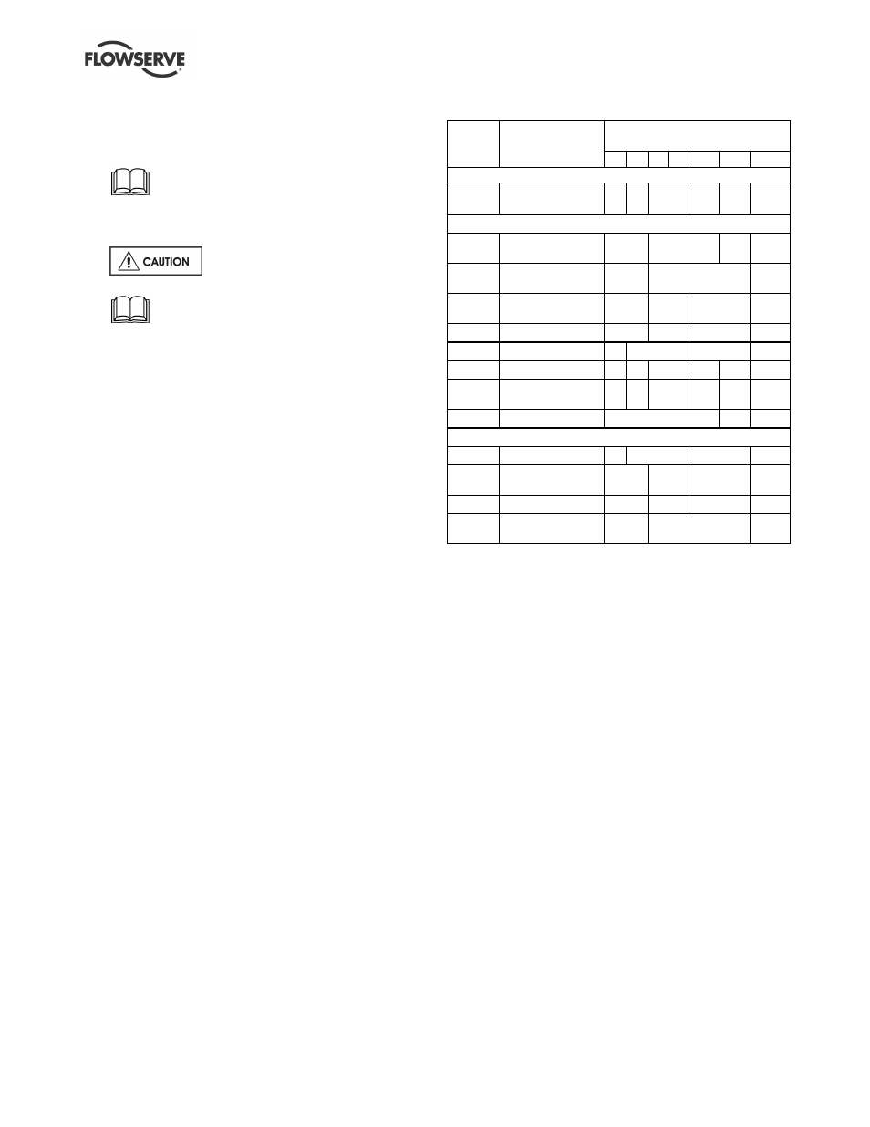
6.4 Recommended spares
Number of pumps
(including stand-by)
Part no. Designation
2
3
4
5
6/7
8/9
10(+)
For start up purposes
4590
Pump casing
gasket
4
6
8
9
12
150%
2 to 4 years operation
2200
Integral stubshaft
and impeller
1
2
3
30%
7120
Muff coupling
(halves)
2
4
20%
9906/04
Coupling grub
screw
1
2
3
50%
9951/02
Adjustment stud
1
2
3
50%
4200
Mechanical seals
1
2
3
30%
4300
Lip seal *
4
6
8
9
10
100%
4590
Pump casing
gasket
4
6
8
9
12
150%
8100
Motor
-
1
2
Optional for start up purposes
4200
Mechanical seals
1
2
3
30%
9906/04
Coupling grub
screw
1
2
3
50%
9951/02
Adjustment stud
1
2
3
50%
7120
Muff coupling
(halves)
2
4
20%
* Where fitted.
6.5 Tools required
A typical range of tools that will be required to
maintain these pumps is listed below.
Readily available in standard tool kits, and dependent
on pump size:
•
Open ended spanners (wrenches) to suit up to
M 20 screws/nuts
•
Socket spanners (wrenches), up to M 20 screws
•
Allen keys, up to 10 mm (A/F)
•
Range of screwdrivers
•
Soft mallet
More specialized equipment:
•
Bearing pullers
•
Bearing induction heater
•
Dial test indicator
•
C-spanner (wrench) - for removing shaft nut.
(If difficulties in sourcing are encountered, consult
Flowserve.)
•
Tapered seal fitting tools for rubber bellows seals