6 fastener torques, 7 setting impeller clearance – Flowserve CPXM User Manual
Page 19
CPXM and CPXRM USER INSTRUCTIONS ENGLISH 71569101 10-08
Page 19 of 32
flowserve.com
6.6 Fastener torques
Screw position
Screw size
Torque Nm (lbf·ft)
Casing and
seal cover
M8
M10
M12
M16
M20
16 (12)
25 (18)
35 (26)
80 (59)
130 (96)
Muff coupling
M8
M10
30 (22)
58 (43)
Cartridge seal sleeve
(where applicable)
M5
M8
5.5 (7) *
16 (22) *
* Where a torque wrench is unavailable, slightly tighten the
setscrews to centralize the cartridge seal, then tighten with a T-bar
until a torsional twist between 60 and 90 degrees is achieved. The
torque applied will be approximate to that recommended.
Non-metalic gaskets incur creep
relaxation - before commissioning the pump check
and retighten fasteners to tightening torques stated.
6.7 Setting impeller clearance
This procedure may be required after the pump has
been dismantled or a different clearance is required.
Before carrying out this procedure ensure that the
mechanical seal(s) fitted can tolerate a change in
their axial setting, otherwise it will be necessary to
dismantle the unit and reset the seal axial position
after adjusting the impeller clearance.
If a cartridge seal is fitted loosen it from the shaft.
6.7.1 Setting CPXM impeller clearance
a) Disconnect the muff coupling and clean up the
bores.
b) Clean motor shaft and stubshaft and deburr
where necessary.
c) Replace muff coupling, ensuring that the
grubscrew locates in the stubshaft.
d) The motor end coupling bolts should be slacker
than the pump end coupling bolts so that the
coupling and stubshaft can be rotated relative to
the motor shaft.
e) The motor shaft should be prevented from
rotating by using a C-spanner located in the
keyway (where possible) or by locking the fan
end of the motor.
f) Rotate the coupling until the impeller contacts the
pump casing. This is the zero clearance position
or datum for setting the front clearance.
g) Mark the bracket with a pen and, whilst preventing
the motor shaft rotating, turn the coupling in the
opposite direction by the recommended number of
notches as indicated in the table. For the
remaining steps, take care not to rotate the pump
shaft relative to the motor shaft.
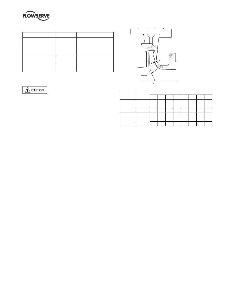
Clearance settings:
Motor frame size
Impeller
diameter
80
90
100 112 132 160 180 200
Clearance
(mm)
0.3 0.3
0.3 0.3 0.3 0.3 0.3 0.3
Up to
210 mm
Notches
7
7
7
7
7
8
8
8
Clearance
(mm)
0.4 0.4
0.4 0.4 0.4 0.4 0.4 0.4
211 to
315 mm
Notches
8
8
8
8
8
9
9
9
h) Carefully loosen and back off the grubscrew and
tighten the coupling bolts, ensuring that the gap
is equal between the coupling halves.
i)
Torque the screws to the specified values:
M 8 - 30 Nm (22 lbf•ft)
M 10 - 58 Nm (43 lbf•ft)
j)
Check that the shaft can turn freely without binding.
k) If a cartridge seal is fitted it should be reset at this
point.
6.7.2 Setting CPXRM impeller clearance
The impeller does not have a fine front clearance
setting and adjustment of the impeller is not normally
required.
a) Disconnect the muff coupling and clean up the
bores.
b) Clean motor shaft and stubshaft and deburr
where necessary.
c) Replace muff coupling, ensuring that the
grubscrew locates in the stubshaft.
d) The motor end coupling bolts should be slacker
than the pump end coupling bolts so that the
coupling and stubshaft can be rotated relative to
the motor shaft.
e) The motor shaft should be prevented from rotating
by using a C-spanner located in the keyway (where
possible) or by locking the fan end of the motor.
f)
With the casing removed, rotate the coupling until
the back clearance is 1.5 to 2 mm (0.06 to 0.08 in.)
as illustrated. This is the setting position and, for
the remaining steps, take care not to rotate the
pump shaft relative to the motor shaft.