7 stopping and shutdown (all series), 8 hydraulic, mechanical and electrical duty – Flowserve WR User Manual
Page 15
WR and CR USER INSTRUCTIONS ENGLISH 26999968 10-12
Page 15 of 28
flowserve.com
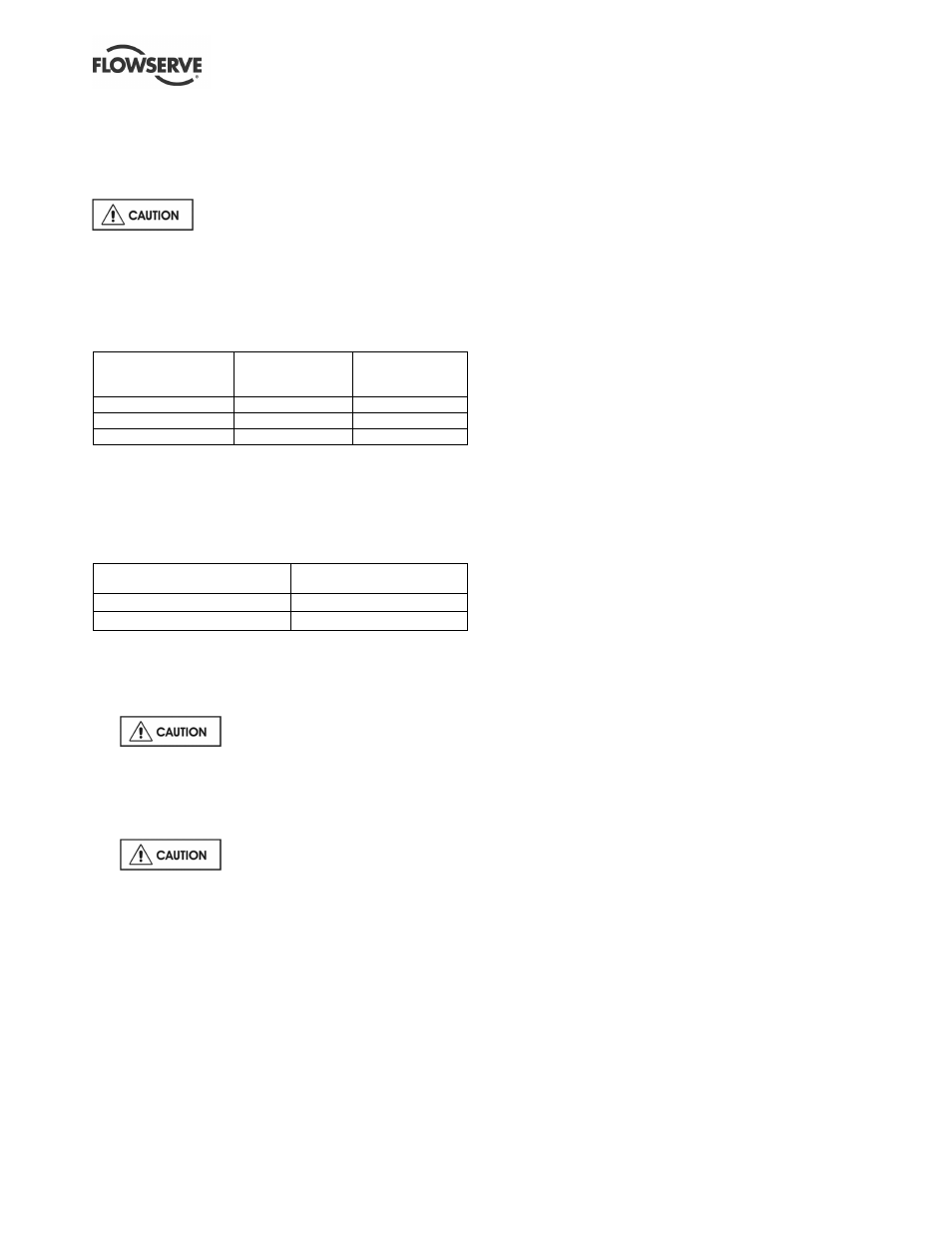
5.6.3 Normal vibration levels, alarm and trip
For guidance, pumps generally fall under a classification
for rigid support machines within the International
rotating machinery standards and the recommended
maximum levels below are based on those standards.
Alarm and trip values for installed pumps
should be based on the actual measurements (N) taken
on the pump in the fully commissioned as new condition.
Measuring vibration at regular intervals will then show
any deterioration in pump or system operating
conditions.
Vibration velocity –
unfiltered
Horizontal pumps
≤≤≤≤
15 kW mm/sec
(in./sec) r.m.s.
> 15 kW
mm/sec (in./sec)
r.m.s.
Normal N
≤
3.0 (0.12)
≤
4.5 (0.18)
Alarm N x 1.25
≤
3.8 (0.15)
≤
5.6 (0.22)
Shutdown trip N x 2.0
≤
6.0 (0.24)
≤
9.0 (0.35)
5.6.4 Stop/start frequency
Pump sets are normally suitable for the number of
equally spaced stop/starts per hour shown in the
table below. Check capability of the driver and
control/starting system before commissioning.
Motor rating kW (hp)
Maximum stop/starts
per hour
Up to 15 (20)
15
Between 15 (20) and 45 (60)
10
Where duty and standby pumps are installed it is
recommended that they are run alternately every week.
5.7 Stopping and shutdown (all series)
a)
Close the outlet valve, but ensure
that the pump runs in this condition for no more
than a few seconds.
b) Stop the pump.
c) Switch off flushing and/or cooling/heating liquid
supplies at a time appropriate to the process.
d)
For prolonged shut-downs and
especially when ambient temperatures are likely
to drop below freezing point, the pump and any
cooling and flushing arrangements must be
drained or otherwise protected.
5.8 Hydraulic, mechanical and electrical
duty
This product has been supplied to meet the performance
specifications of your purchase order, however it is
understood that during the life of the product these may
change. The following notes may help the user decide
how to evaluate the implications of any change. If in
doubt contact your nearest Flowserve office.
5.8.1 Specific gravity (SG)
Pump capacity and total head in metres (feet) do not
change with SG, however pressure displayed on a
pressure gauge is directly proportional to SG. Power
absorbed is also directly proportional to SG. It is
therefore important to check that any change in SG
will not overload the pump driver or over-pressurize
the pump.
5.8.2 Viscosity
For a given flow rate the total head reduces with
increased viscosity and increases with reduced
viscosity. Also for a given flow rate the power
absorbed increases with increased viscosity, and
reduces with reduced viscosity. It is important that
checks are made with your nearest Flowserve office if
changes in viscosity are planned.
5.8.3 Pump speed
Changing pump speed effects flow, total head, power
absorbed, NPSH
R
, noise and vibration. Flow varies in
direct proportion to pump speed, head varies as speed
ratio squared and power varies as speed ratio cubed.
The new duty, however, will also be dependent on the
system curve. If increasing the speed, it is important
therefore to ensure the maximum pump working
pressure is not exceeded, the driver is not overloaded,
NPSH
A
> NPSH
R
, and that noise and vibration are
within local requirements and regulations.
5.8.4 Net positive suction head (NPSH
A
)
NPSH available (NPSH
A
) is a measure of the head
available in the pumped liquid, above its vapour
pressure, at the pump suction branch.
NPSH required (NPSH
R
) is a measure of the head
required in the pumped liquid, above its vapour
pressure, to prevent the pump from cavitating. It is
important that NPSH
A
> NPSH
R
. The margin between
NPSH
A
> NPSH
R
should be as large as possible.
If any change in NPSH
A
is proposed, ensure these
margins are not significantly eroded. Refer to the
pump performance curve to determine exact
requirements particularly if flow has changed.
If in doubt please consult your nearest Flowserve
office for advice and details of the minimum allowable
margin for your application.
5.8.5 Pumped flow
Flow must not fall outside the minimum and
maximum continuous safe flow shown on the pump
performance curve and or data sheet.