Flowserve PLEUGER User Manual
Page 25
PLEUGER STANDARD USER INSTRUCTIONS ENGLISH 71569293 01-13
Page 25 of 40
flowserve.com
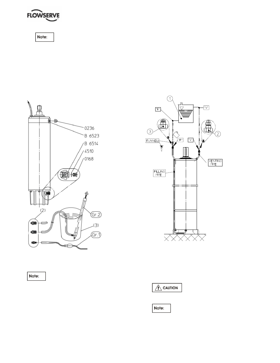
The connections of the filling nipple [2]
are different sizes. Fit the relevant filling nipple
[M10 or M16] into the threaded hole.
e) Fit the hose end of the filling pump over the
nipple [2] and place the pump into a container [3]
filled with the filling liquid.
f) Fill the motor until the liquid escapes from the
vent valve [B6523] with no bubbles.
g) Pull the pump hose off the nipple and screw out
the nipple.
h) Refit the screw plug [0168] into the filling valve
[B6514] together with the seal ring [4510].
Figure 6-2
6.6.3 Motors with header tank for vertical
installation
(See figure 6-3.)
Motors for this type of installation are
specially equipped.
a) Position the motor vertically and prevent the unit
from falling over.
b) Screw out the adapter with vent valve [2] from the
vent pipe “V”.
c) Remove the adapter and plug [3] from the filing
pipe “F”.
d) Fill the motor before installation using a funnel [4]
into filling pipe “F” until the liquid escapes with no
bubbles from vent pipe “V”.
e) Install the motor and fill the connected filling and
venting pipes during installation. (If using
multiple pipes it is advisable to fill the subsequent
pipes with liquid immediately after fitting to test
the connections for leakage.)
f) After installing the header tank [1] and connecting
the pipes to it, fill the tank with liquid up to the
mark indicated. When filling the tank, ensure that
no liquid enters the vent pipe “V”.
6.6.4 Filling and topping up units with cooling/
suction shroud
(See figure 6-4.)
a) Position the unit vertically and prevent the unit
from falling over.
b) Remove the inner screw plug [0168] of the filling
valve [B6514].
Handle seal ring [4510] with care.
c) Screw the filling nipple into the threaded hole
from which the screw plug [0168] was removed.
The hose connections of the filling
nipples [2] are different sizes. The correct one for
the thread size (M10 or M16) and the pump hose
must be fitted.
Figure 6-3