6 installation of pre-assembled pump units, 7 riser pipes with flange connections, 8 riser pipe with pipe socket – Flowserve PLEUGER User Manual
Page 15: 9 assembly of submersible motor pumps, Before installation, 5 electrical connections
PLEUGER STANDARD USER INSTRUCTIONS ENGLISH 71569293 01-13
Page 15 of 40
flowserve.com
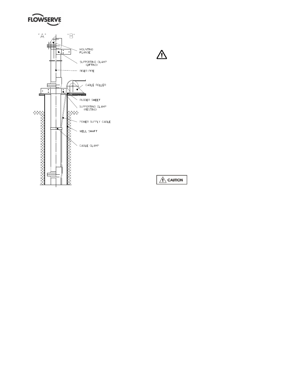
Figure 4-1
4.6 Installation of pre-assembled pump
units
Mount the first length of pipe, which should not be
longer than 1 m (39 in.), onto the assembled pump unit.
Fasten the power cables, control lines and instrument
leads (if any) with cable clips onto the pipe.
4.7 Riser pipes with flange connections
(Reference “A” in figure 4-1.)
a) Mount a "lifting dolly
” to the riser pipe flange, and
hang the complete unit on a suitable hoist.
b) Lower the pump unit into the well, allowing
sufficient pipe to protrude above the well to
enable the installation clamp to be mounted onto
the riser pipe.
c) Continue to lower the unit until the installation
clamp rests on the well rim flange.
d) Remove the lifting dolly, and attach it to the next
riser pipe to be installed.
e) Fasten the power cable, control lines and
instrument leads (if any) with cable clips to the
riser pipe.
f) Lift the next pipe to be installed into a vertical
position and bolt it to the pipe resting on the well
rim flange.
g) When this has been completed lift the unit
sufficiently to enable the supporting clamp to be
removed.
Do not allow the pipe to be lowered or to
slip whilst carrying out this operation. This could
result in damage to hands and in extreme cases
loss of fingers.
h) Install the remaining riser pipes as described
from point b) to e).
i)
Finally mount the wellhead support plate onto the
last length of riser pipe. Feed the power cables
and, if necessary, the control lines and/or
instrument leads through the corresponding holes
in the wellhead support plate and connect them
to the junction box or control panel.
4.8 Riser pipe with pipe socket
(Reference “B” in figure 4-1.)
a) Connect a lifting clamp underneath the pipe
socket of the screwed riser pipe and lift the
complete pump unit with a suitable hoist.
b) Lower the pump unit into the well as far as the
installation clamp mounted underneath the socket
of the riser pipe.
c) Lower the unit and rest it on the well rim flange.
Do not let the pump unit slip
through the installation clamp.
j)
Remove the lifting clamp and attach it to the next
riser pipe and connect this to the pipe already
installed.
k) Fasten the power cables and, if necessary, the
control lines and/or instrument leads with cable
clips onto the riser pipe.
l)
Lift the unit and remove the resting supporting
clamp.
m) Install the remaining riser pipes as described
from point b) to f).
n) Finally mount the wellhead support plate onto the
last riser pipe. Feed the power cables and, if
necessary, the control lines and/or instrument
leads through the corresponding holes in the
wellhead support plate and connect them to the
junction box or control panel.
4.9 Assembly of submersible motor
pumps before installation
Submersible motor pump units that are delivered in
sub-assemblies have to be assembled during or
before installation. For assembly of these submersible
motor pump units the specific installation instructions
have to be requested from the manufacturer if they
have not been delivered with the unit.