Flowserve PLEUGER User Manual
Page 24
PLEUGER STANDARD USER INSTRUCTIONS ENGLISH 71569293 01-13
Page 24 of 40
flowserve.com
In special cases the filling instructions must be
requested from the manufacturer.
Table 6-7
Mo
tor
ty
pe
Section numbers
6
.6
.1
6
.6
.2
6
.6
.3
6
.6
.4
6
.6
.5
6
.6
.6
6
.6
.7
6
.6
.8
6
.6
.9
6
.6
.1
0
6
.6
.1
1
M6
•
O
•
•
O
O
•
MP6
O
•
O
O
MX6
•
O
•
•
O
O
•
M8
•
O
•
•
O
O
•
MP8
O
•
O
O
MX8
•
O
•
•
O
O
•
MI10
•
O
•
•
O
O
•
MIP10
O
•
O
O
MIX10
•
O
•
•
O
O
•
VNI12
•
O
•
•
O
O
•
VNI14
•
O
•
•
•
O
O
•
MI16
•
O
•
•
•
O
O
•
MI19
•
O
VNI22
•
O
MI26
•
O
VNI30
•
O
•
= standard
O = optional
Not currently
scheduled
The following instructions are only relevant for filling
and topping up before the first installation, for motors
without a header tank. Before installation ensure that
the motors do not have any leaks.
For installations with a header tank, the liquid level
must be monitored. Installation of an automatic level
control is recommended.
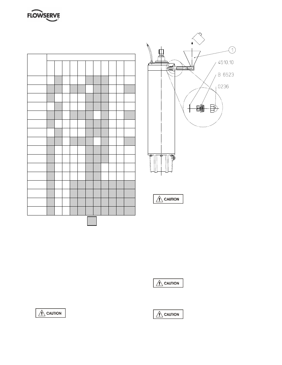
6.6.1 Filling and topping up with a funnel
(See figure 6-1.)
a) Position the motor vertically and prevent the unit
from falling over.
b) Remove the cap [0236] of the vent valve [B6523]
with a screwdriver or similar tool.
The cap [0236] is only used for
protection during transportation and must always
be removed before installation.
c) Screw out the vent valve [B6523] with a ring
wrench or socket wrench (size 17).
Handle seal ring [4510.10] with
care.
d) Fit together the two-part funnel [1], and insert it
into the threaded hole of the removed vent valve.
e) Fill or top up until liquid escapes from the vent
opening.
f) Screw the vent valve [B6523] back in with its seal
ring [4510.10].
6.6.2 Filling and topping up with filling pump
(See figure 6-2.)
a) Position the motor vertically and prevent the unit
from falling over.
b) Remove the cap [0236] of the vent valve [B6523]
with a screwdriver or similar tool.
The cap [0236] is only used for
protection during transportation and must always
be removed before installation.
c) Screw out the inner screw plug [0168] of the
filling valve [B6514].
Handle seal ring [4510] with care.
d) Screw the filling nipple supplied [2] into the screw
plug threaded hole.
Figure 6-1