Examination of parts, Assembly, Assembly (6.10) – Flowserve LNN User Manual
Page 32: Examination of parts (6.9), Reassembly (see 6.10, assembly)
LNN, LNNV, LNNC USER INSTRUCTIONS ENGLISH 71569074 06-14
Page 32 of 56
flowserve.com
b)
When removing the rotor unit, the casing wear
rings [1500] will be attached to it as they are fixed
by two diametrically opposite pins [6811.1]
inserted into the casing ring and located in
grooves in the lower half casing.
c)
If impeller rings [2300] are also fitted, they are
shrunk onto the impeller and fixed with grub
screws [6814.1] between their diametral mating
surfaces.
d)
To remove the impeller rings, remove the locking
screws and heat up the ring until it slides off easily.
6.9 Examination of parts
Used parts must be inspected before
assembly to ensure the pump will subsequently run
properly. In particular, fault diagnosis is essential to
enhance pump and plant reliability.
6.9.1
Casing, seal housing and impeller
Inspect for excessive wear, pitting, corrosion, erosion or
damage and any sealing surface irregularities.
Replace
as necessary.
6.9.2
Shaft and sleeve (if fitted)
Replace if grooved, pitted or worn.
6.9.3
Gaskets and O-rings
After dismantling, discard and replace.
6.9.4
Bearings
It is recommended that bearings are not re-used after
any removal from the shaft.
The plain liquid lubricated bearings may be re-used if
both the bearing bush and bearing sleeve show no
sign of wear, grooving or corrosion attack. (It is
recommended that both the bush and sleeve are
replaced at the same time.)
6.9.5
Bearing isolators, labyrinths or lip seals
(if fitted)
a) The lubricant, bearings and bearing housing
seals are to be inspected for contamination and
damage. If oil bath lubrication is utilized, these
provide useful information on operating
conditions within the bearing housing.
b)
If bearing damage is not due to normal wear and
the lubricant contains adverse contaminants, the
cause should be corrected before the pump is
returned to service.
c)
Labyrinth seals and bearing isolators should be
inspected for damage but are normally non-
wearing parts and can usually be re-used.
d)
Bearing seals are not totally leak free devices.
Oil from these may cause staining adjacent to the
bearings.
6.10 Assembly
To assemble the pump consult the sectional
drawings, see section 8, Parts list and drawings.
Ensure threads, gasket and O-ring mating faces are
clean and that ball bearings are C3 fit. Apply thread
sealant to non-face sealing pipe thread fittings.
6.10.1 Wear rings
a)
Impeller rings (when fitted) should be heated up
using a hotplate or hot oil bath and then slipped
onto the impeller and pressed down to the
shoulder. (Do NOT use a steel hammer to knock
them into position.)
b)
Drill and tap 3 holes approximately 120 degrees
apart into the diameter between the mating faces
of the ring and impeller and insert grub screws.
(The existing half tapped holes from the removed
impeller ring cannot be re-used.)
6814.1
2300
2200
c)
Slip the casing wear rings over the impeller hubs
before mounting the rotor unit into the lower half
casing, ensuring the pins in the rings locate into
the holes in the casing.
d)
Check the running clearance between impeller
and casing ring against the appropriate pump
size in section 3.4.2.
6 8 1 1 . 1
1 5 0 0
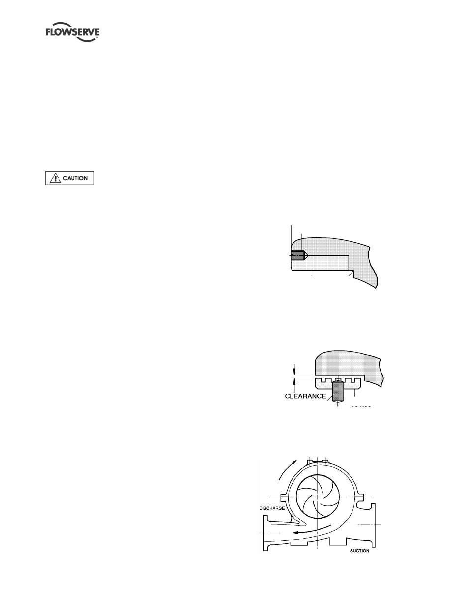
6.10.2 Impeller setting
a)
When re-assembling the impeller on the shaft, it is
important to mount the impeller so that the vane tips
point away from the apparent flow direction.