Flowserve LNN User Manual
Page 18
LNN, LNNV, LNNC USER INSTRUCTIONS ENGLISH 71569074 06-14
Page 18 of 56
flowserve.com
4.6.3
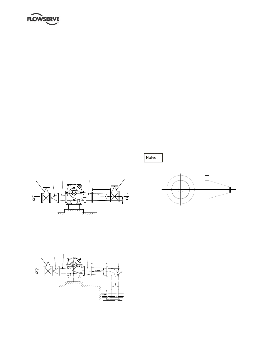
Suction piping
Refer to the diagrams below for typical designs of
suction piping for both flooded suction and suction lift.
a) The inlet pipe should be one or two sizes larger
than the pump inlet bore and pipe bends should
be as large a radius as possible.
b) Pipe work reducers should be conical and have a
maximum total angle of divergence of 15 degrees.
c)
On suction lift the piping should be inclined up
towards the pump inlet with eccentric reducers
incorporated to prevent air locks.
d)
On positive suction, the inlet piping must have a
constant fall towards the pump.
e) Flow should enter the pump suction with uniform
flow, to minimize noise and wear. This is
particularly important on large or high-speed
pumps which should have a minimum of five
diameters of straight pipe on the pump suction
between the elbow and inlet flange. See section
10.3, Reference 1, for more detail.
f) Do not install elbows at an angle other than
perpendicular to the shaft axis. Elbows parallel
to the shaft axis will cause uneven flow.
Typical design
– flooded suction
Discharge
isol ati ng
val ve
No n
ret ur n
val ve
Conce nt r ic
conic al
red ucer
Eccent r ic
conic al
red ucer
Suc tio n
isol ati ng
val ve
S l op e up f r om
p um p s uc t i o n
Note:
Ideally reducers should be limited to one pipe diameter change,
ie 150 mm (6 in.) to 200 mm (8 in.). Must have a maximum total
angle of divergence of 15 degrees.
Typical design
– suction lift
L o n g
r a d i u s
b e n d
S l o p e d o w n
f r o m p u m p
s u c t i o n
> 5 D
E c c e n t r i c
c o n i c a l
r e d u c e r
D i s c h a r g e
i s o l a t i n g
v a l v e
C o n c e n t r i c
c o n i c a l
r e d u c e r
N o n
r e t u r n
v a l v e
Notes:
1. S = Minimum submergence >3E.
2. Ideally reducers to be limited to one pipe diameter change,
ie 150 mm (6 in.) to 200 mm (8 in.). Must have a maximum total
angle of divergence of 15 degrees.
g)
Except in unusual circumstances strainers are
not recommended in inlet piping. If considerable
foreign matter is expected a screen installed at
the entrance to the wet well is preferable.
h)
Inlet strainers, when used, should have a net ‘free
area’ of at least three times the inlet pipe area.
i)
Fitting an isolation valve will allow easier
maintenance.
j)
Never throttle pump on suction side and never
place a valve directly on the pump inlet nozzle.
4.6.3.1
Suction strainer
In a new installation, great care should be taken to
prevent dirt, scale, welding beads and other items
from entering the pump, as it is particularly important
to protect the numerous close running fits from
abrasive matter present in new piping
The suction system should be thoroughly flushed
before installing the suction strainer and making up
suction piping to the pump. The suction strainer
should be installed between 5 to 20 pipe diameters
upstream from the pump suction flange.
The open area of the strainer should
have a minimum of a 3 to 1 ratio to the area of the
pump suction.
Cone type strainer
The Flowserve recommendation for suction strainers
consists of a conical shaped steel plate. The plate has
1.6 mm (
1
/
16
in.) perforations and is of sufficient size and
thickness for the required flow. (See figure above.)
Other type of strainers may be used as long as they
conform to the requirements stated above.
Pressure gauges should be installed on both sides of
the screen so that the pressure drop across the
screen can be measured.
When the unit is being started, the gauges on each
side of the screen should be carefully watched. An
increase in the differential pressure between the two
gauges indicates that the screen is becoming clogged
with dirt and scale. At this point, the pump should be
shut down, and the screen cleaned and/or replaced.
The strainer must be removed after the initial run-in
time if the process does not allow its permanent use.
>5D