Renewal clearances, Disassembly, Clearances (see 6.7, renewal clearances) – Flowserve LNN User Manual
Page 30: Disassembly (6.8), Dismantling (see 6.8, disassembly), Impeller clearance (6.7), 7 renewal clearances, 8 disassembly
LNN, LNNV, LNNC USER INSTRUCTIONS ENGLISH 71569074 06-14
Page 30 of 56
flowserve.com
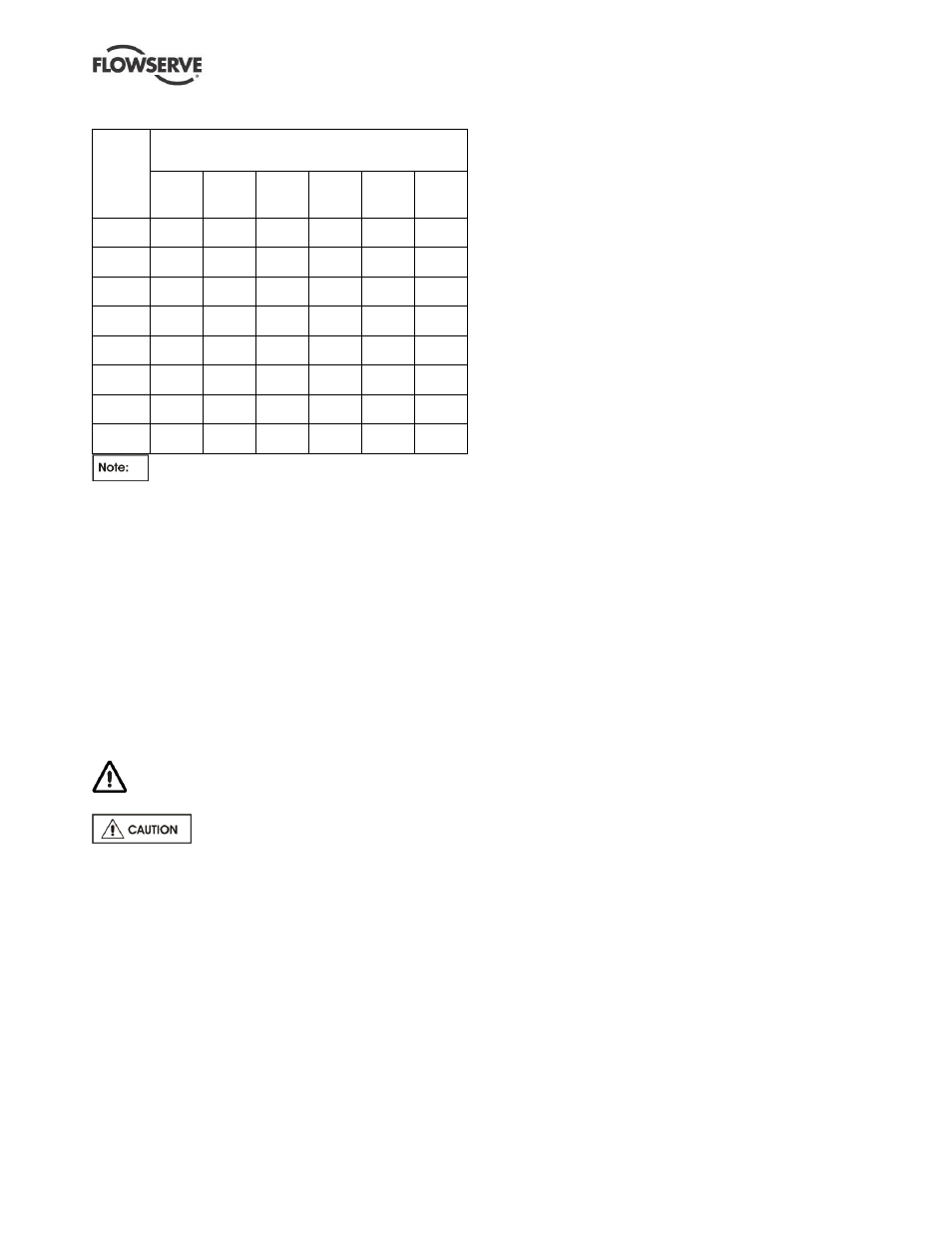
6.6.2
Other bolt locations
Bolt
size
Torque
Nm (lbf•ft) - other bolt locations
Class
8.8
Class
6.8
Dupl
Class
5.8
A193
Gr B7M
316 SS
A4-80
M 16
(⅝ in.)
160
(120)
120
(90)
100
(80)
135
(100)
45
(40)
150
(120)
M 20
(¾ in.)
310
(230)
233
(180)
194
(150)
262
(200)
87
(70)
291
(220)
M 24
(⅞ in.)
535
(400)
401
(300)
334
(250)
451
(340)
150
(120)
502
(380)
M 27
(1 in.)
785
(580)
589
(440)
491
(370)
662
(490)
221
(170)
736
(550)
M 30
(1⅛ in.)
1100
(820)
825
(610)
688
(510)
928
(690)
309
(230)
1031
(770)
M 36
(1⅜ in.)
1850
(1370)
1388
(1030)
1156
(860)
1561
(1160)
520
(390)
1734
(1280)
M 42
(1⅝ in.)
3000
(2220)
2250
(1660)
1875
(1390)
2531
(1870)
844
(630)
2813
(2080)
M 48
(1⅞ in.)
4500
(3320)
3375
(2490)
2813
(2080)
3797
(2810)
1266
(940)
4219
(3120)
For the tightening sequence also refer to good
industry practice. See section 10.3, Reference 6, for
more detail.
6.7 Renewal clearances
As wear takes place between the impeller and casing
wear ring the overall efficiency of the pump set will
decrease. To maintain optimum efficiency it is
recommended that rings are replaced and the impeller
renovated when the radial clearance detailed in section
3.4.2 has doubled to 0.6 to 0.8 mm (0.024 to 0.032 in.),
depending on pump size. On the LNNV it is
recommended that the product lubricated bearing is
renewed at a diametrical clearance of 0.5 mm (0.02 in.).
6.8 Disassembly
Refer to section 1.6, Safety, before dismantling
the pump.
Before dismantling the pump for
overhaul, ensure genuine Flowserve replacement
parts are available.
Refer to sectional drawings for part numbers and
identification. See section 8, Parts lists and drawings.
6.8.1
Rotor unit
6.8.1.1
LNN and LNNC
a) Isolate motor and lock off electrical supply in
accordance with local regulations.
b) Isolate suction and discharge valves.
c)
Remove coupling guards and disconnect the
coupling halves.
d)
Drain pump casing. Remove any auxiliary piping
if applicable.
e) Unscrew and remove bearing housing setscrews
[6570.4].
f)
Unscrew and remove nuts [6580.1 or 6580.4]
above split flange on upper half casing. Drive out
dowel pin [6810] (if fitted) from casing flange
halves. Remove upper half casing [1214].
g)
Take out complete rotor unit and place onto two
support blocks.
6.8.1.2
LNNV
This pump is best removed from the system to carry out
complete strip down. It should be set down with the
shaft horizontal to enable the rotor to be removed.
a) Isolate motor and lock off electrical supply in
accordance with local regulations.
b) Isolate suction and discharge valves.
c)
Remove coupling guards and disconnect the
coupling halves.
d) Drain pump casing and, if applicable, remove any
auxiliary piping.
e) Remove motor complete with motor stool and set
down carefully in a safe location.
f) Retain any shimming between stool and pump
casing.
g) Remove bolts securing pump suction and
discharge flanges.
h) Sling pump as shown in section 2.3 and take the
strain. Remove setscrews securing the pump
baseplate to the pump casing.
i)
Remove the pump to a safe location and
manoeuvre the pump shaft into a horizontal position.
j)
Unscrew and remove setscrews [6570.4 and
6570.5] securing the bearing housing and end
cover [3200 and 3266]. Remove end cover.
k) Unscrew and remove nuts
[6580.5] above split
flange on upper half casing. If fitted to casing
flange halves, drive out dowel pin [6810].
l)
Using jacking screws, remove upper half casing.
m) Carefully remove non-drive end stuffing box
housing [4110] complete with bearing housing
[3200] and bearing bush [3300]. The impeller
now rests on the casing ring.
n) Carefully take out complete rotor assembly.
Protect the bearing surface on the outside
diameter of the bearing sleeve [3400] from
damage and place rotor on two support blocks.
o) If supplied with optional grease lubricated bottom
line bearing, carefully remove the complete rotor
assembly after l) above and the upper half casing
has been removed.
6.8.2
Bearing housing
a) Remove bearing cover setscrews [6570.6] and
remove key [6700.2] from shaft end.
b) Remove shaft seal ring [4305.2] and pull off bearing
housing [3200] from the rotor.