Spare parts, Recommended spares and consumable items, Tools required – Flowserve LNN User Manual
Page 29: Fastener torques, Fastener torques (6.6), Ordering spare parts (6.3.1), Recommended spares (6.4), Replacement parts (see 6.3 and 6.4), Spare parts (6.3), Storage, spare parts (6.3.2)
LNN, LNNV, LNNC USER INSTRUCTIONS ENGLISH 71569074 06-14
Page 29 of 56
flowserve.com
Any loss of coating material is considered to be
normal wear and tear on the pump and is not
considered as warranty. Flowserve has applied the
coatings according to the supplier's instructions but
will not be held responsible for coating wear or cracks
that may develop over time.
6.3 Spare parts
6.3.1
Ordering of spares
Flowserve keep records of all pumps that have been
supplied. When ordering spares the following
information should be quoted:
1)
Pump serial number.
2)
Pump size.
3)
Part name – taken from section 8.
4)
Part number – taken from section 8.
5)
Number of parts required.
The pump size and serial number are shown on the
pump nameplate.
To ensure continued satisfactory operation,
replacement parts to the original design specification
should be obtained from Flowserve. Any change to
the original design specification (modification or use
of a non-standard part) will invalidate the pump’s
safety certification.
6.3.2
Storage of spares
Spares should be stored in a clean dry area away
from vibration. Inspection and re-treatment of
metallic surfaces (if necessary) with preservative is
recommended at 6 monthly intervals
6.4 Recommended spares and
consumable items
For start-up purposes:
1 - complete set of gland packing
2 - shaft sleeves
1 - set of gaskets and seals
(optional: 2 - mechanical seals)
For 2 years operation:
1 - set of bearings (line and thrust)
2 - sets of gland packing
2 - shaft sleeves
2 - sets of gaskets and seals
2 - lantern rings
2 - casing wear rings
(optional: 2 - mechanical seals
2 - impeller wear rings)
For 4 years operation:
1 - set of bearings (line and thrust)
2 - sets of gland packing
2 - shaft sleeves
2 - sets of gaskets and seals
2 - lantern rings
2 - casing wear rings
1 - impeller
(optional: 2 - mechanical seals
2 - impeller wear rings)
6.5 Tools required
A typical range of tools that will be required to
maintain these pumps is listed below.
Readily available in standard tool kits, and dependent
on pump size:
Open ended spanners (wrenches) to suit up to
M 48 screws/nuts
Socket spanners (wrenches), up to M 48 screws
Allen keys, up to 10 mm (A/F)
Range of screwdrivers
Soft mallet
More specialized equipment:
Bearing pullers
Bearing induction heater
Dial test indicator
C-spanner (wrench) - for removing shaft nut.
(If difficulties in sourcing are encountered,
consult Flowserve.)
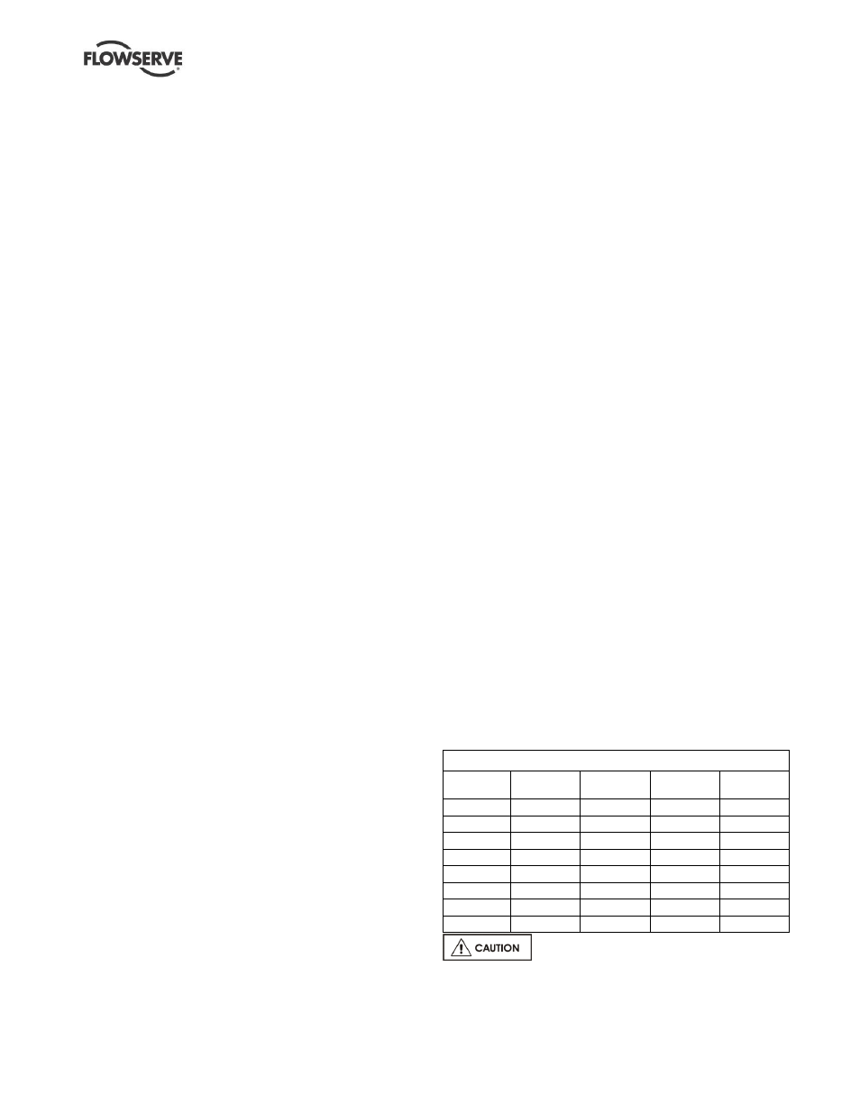
6.6 Fastener torques
6.6.1
Pump split case bolts and pump foot
bolts
The standard bolt class is A4-80, 8.8 or higher with
lubricated thread (600 MPa and 640 MPa yield
strength respectively or higher). Unless otherwise
specified on the pump GA drawing, the following
torques shall be applied on the pump foot bolts and
pump split case bolts:
Torque Nm (lbf•ft) for pump foot and split casing bolts
Bolt size
Class 8.8
Duplex and
super duplex
A193 Gr
B7M
A4-80
M 16 (⅝ in.)
160 (120)
113 (90)
135 (100)
150 (120)
M 20 (¾ in.)
310 (230)
218 (170)
262 (200)
291 (220)
M 24
(⅞ in.)
535 (400)
376 (280)
451 (340)
502 (380)
M 27 (1 in.)
785 (580)
552 (410)
662 (490)
736 (550)
M 30
(1⅛ in.) 1 100 (820)
773 (580)
928 (690)
1 031 (770)
M 36
(1⅜ in.) 1 850 (1 370) 1 301 (960) 1561 (1 160) 1 734 (1 280)
M 42
(1⅝ in.) 3 000 (2 220) 2 109 (1 560) 2 531 (1 870) 2 813 (2 080)
M 48
(1⅞ in.) 4 500 (3 320) 3 164 (2 340) 3 797 (2 810) 4 219 (3 120)
Non-metallic gaskets incur creep
relaxation - before commissioning the pump check
and retighten fasteners to tightening torques stated.