Fastener torques, Setting impeller clearance, Clearances, impeller (6.7) – Flowserve Durco Mark 3 ISO Frame Mounted User Manual
Page 28: Fastener torques (6.6), Setting impeller clearance (6.7), Torques for fasteners (6.6), 6 fastener torques, 7 setting impeller clearance
DURCO MARK 3 ISO FRAME MOUNTED ENGLISH 85392719 12-14
Page 28 of 52
flowserve.com
More specialized equipment:
Bearing pullers
Bearing induction heater
Dial test indicator
C-spanner (wrench) - for removing shaft nut.
(If difficulties in sourcing are encountered, consult
Flowserve.)
Coupling grip/shaft spanner
6.6 Fastener torques
Fastener
Screw size
Torque Nm (lbf•ft)
All except where
otherwise stated
M8
M10
M12
M16
M20
16 (12)
25 (18)
35 (26)
80 (59)
130 (96)
Impeller nut
M12
M16
M22
M24
16 (12)
41 (31)
106 (79)
135 (100)
For the tightening sequence also refer to good
industry practice. See section 10.3, Reference 6, for more
detail.
Non-metallic gaskets incur creep
relaxation - before commissioning the pump check and
retighten fasteners to tightening torques stated.
6.7
Setting impeller clearance
This procedure may be required after the pump has
been dismantled or a different clearance is required.
Before carrying out this procedure ensure that the
mechanical seal(s) [4200] fitted can tolerate a change in
their axial setting, otherwise it will be necessary to
dismantle the unit and reset the seal axial position after
adjusting the impeller clearance.
a) Disconnect the coupling if it has limited axial flexibility.
b)
The impeller adjustment is easily made externally
by loosening the screws [6570.1/2] and rotating the
bearing carrier [3240] to obtain the proper
clearance.
6.7.1
Setting open impeller (OP) front clearance
a)
Turn the bearing carrier [3240] clockwise until the
impeller [2200] comes into light contact with the
front profile on the casing [1100]. Rotating the shaft
[2100] at the same time will accurately determine
when a detectable rub is obtained. This is the zero
clearance setting.
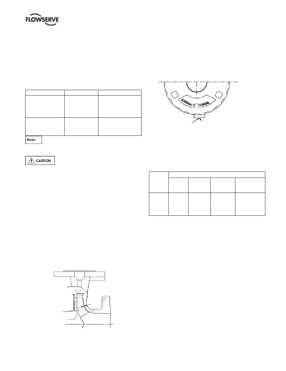
b)
Rotating the bearing carrier [3240] the width of one of
the indicator patterns cast into the bearing carrier
moves the impeller [2200] axially 0.1 mm (0.004 in.).
Example: for an impeller setting of 0.4 mm, (0.016 in.)
simply move the bearing carrier [3240]
counterclockwise four indicator patterns for the
required clearance.
c)
Use the indicator pattern closest to the top center of
the bearing housing as the reference point to begin
adjustment.
Temp
ºC
(ºF)
Clearance mm (in.)
Impellers
up to
210 mm
Impellers
211 mm to
260 mm
Impellers
over 260 mm
(except *)
(*) 150-400
(*) 200-400
(*) 150-500
50 (122)
100 (212)
150 (302)
200 (392)
250 (482)
0.3 (0.012)
0.4 (0.016)
0.5 (0.020)
0.6 (0.024)
0.7 (0.028)
0.4 (0.016)
0.5 (0.020)
0.6 (0.024)
0.7 (0.028)
0.8 (0.032)
0.5 (0.020)
0.6 (0.024)
0.7 (0.028)
0.8 (0.032)
0.9 (0.036)
1.0 (0.040)
1.0 (0.040)
1.1 (0.044)
1.2 (0.048)
1.3 (0.052)
d) After obtaining the proper clearance, listed in the
table above, tighten the screws [6570.1] evenly to
lock the impeller [2200] and shaft [2100] assembly.
Tightening the set screws [6570.1] will cause the
impeller to move 0.05 mm (0.002 in.) closer to the
rear cover because of the internal clearance in the
bearing carrier threads. This must be considered
when setting the impeller clearance.
e)
Check that the shaft [2100] can turn freely without
binding.
f)
If a cartridge seal [4200] is fitted it should be reset
at this point.
g)
Ensure the coupling distance between shaft ends
(DBSE) is correct. Reset/re-align if necessary.
6.7.2
Setting reverse vane (RV) impeller rear
clearance
a) Reverse vane impellers are set off the cover. This
allows the impeller to be set without the casing.
Indicator pattern
Rotation equivalent to
0.1 mm axial movement