Stopping and shutdown, Hydraulic, mechanical and electrical duty (5.10), Vibration (5.8.4) – Flowserve Durco Mark 3 ISO Frame Mounted User Manual
Page 24: 9 stopping and shutdown
DURCO MARK 3 ISO FRAME MOUNTED ENGLISH 85392719 12-14
Page 24 of 52
flowserve.com
Care must be taken when adjusting the gland on
an operating pump. Safety gloves are essential. Loose
clothing must not be worn to avoid being caught up by
the pump shaft. Shaft guards must be replaced after
the gland adjustment is complete.
Never run gland packing dry, even for a
short time.
5.8.2
Pumps fitted with mechanical seal
Mechanical seals require no adjustment. Any slight initial
leakage will stop when the seal is run in.
Before pumping dirty liquids it is advisable, if possible, to
run the pump in using clean liquid to safeguard the seal
face.
External flush or quench should be started
before the pump is run and allowed to flow for a period
after the pump has stopped.
Never run a mechanical seal dry, even
for a short time.
5.8.3
Bearings
If the pumps are working in a potentially explosive
atmosphere temperature or vibration monitoring at the
bearings is recommended.
If bearing temperatures are to be monitored it is
essential that a benchmark temperature is recorded at
the commissioning stage and after the bearing
temperature has stabilized.
Record the bearing temperature (t) and the ambient
temperature (ta)
Estimate the likely maximum ambient temperature (tb)
Set the alarm at (t+tb-ta+5) º
C (t+tb-ta+10) ºF and the
trip at 100 ºC (212 ºF) for oil lubrication and 105 ºC
(220 ºF) for grease lubrication
It is important, particularly with grease lubrication, to
keep a check on bearing temperatures. After start up
the temperature rise should be gradual, reaching a
maximum after approximately 1.5 to 2 hours. This
temperature should then remain constant or marginally
reduce with time. Refer to section 6.2.3.2 for further
information.
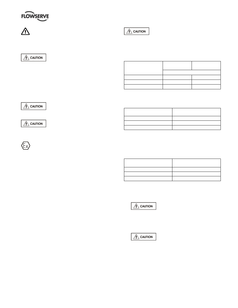
5.8.4
Normal vibration levels, alarm and trip
For guidance, pumps generally fall under a classification
for rigid support machines within the International rotating
machinery standards and the recommended maximum
levels below are based on those standards.
Alarm and trip values for installed pumps
should be based on the actual measurements (N) taken
on the pump in the fully commissioned as new
condition. Measuring vibration at regular intervals will
then show any deterioration in pump or system
operating conditions.
Vibration velocity
–
unfiltered
Horizontal pumps
15 kW (20 hp)
Horizontal pumps
> 15 kW (20 hp)
mm/s (in./sec) r.m.s.
Normal N
3.0 (0.12)
4.5 (0.18)
Alarm N x 1.25
3.8 (0.15)
5.6 (0.22)
Shutdown trip N x 2.0
6.0 (0.24)
9.0 (0.35)
Where a grease lubricated unit is utilized in a vertical
shaft configuration with a duck-foot bend onto the pump
suction, the following apply:
Vibration velocity
– unfiltered
Vertical configurations
mm/s (in./sec) r.m.s.
Normal N
7.1 (0.28)
Alarm N x 1.25
9.0 (0.35)
Shutdown trip N x 2.0
14.2 (0.56)
5.8.5
Stop/start frequency
Pump sets are normally suitable for the number of
equally spaced stop/starts per hour shown in the table
below. Check capability of the driver and
control/starting system before commissioning.
Motor rating kW (hp)
Maximum stop/starts
per hour
Up to 15 (20)
15
Between 15 (20) and 90 (120)
10
Above 90 (120)
6
Where duty and standby pumps are installed it is
recommended that they are run alternately every week.
5.9
Stopping and shutdown
a)
Close the outlet valve, but ensure
that the pump runs in this condition for no more
than a few seconds.
b) Stop the pump.
c) Switch off flushing and/or cooling/heating liquid
supplies at a time appropriate to the process.
d)
For prolonged shut-downs and
especially when ambient temperatures are likely to
drop below freezing point, the pump and any cooling
and flushing arrangements must be drained or
otherwise protected.