Mechanical installation, Tank, Engine – Floscan FloNET Standard Flow Model User Manual
Page 14
06/02/2011
4001-443-00B
MECHANICAL INSTALLATION
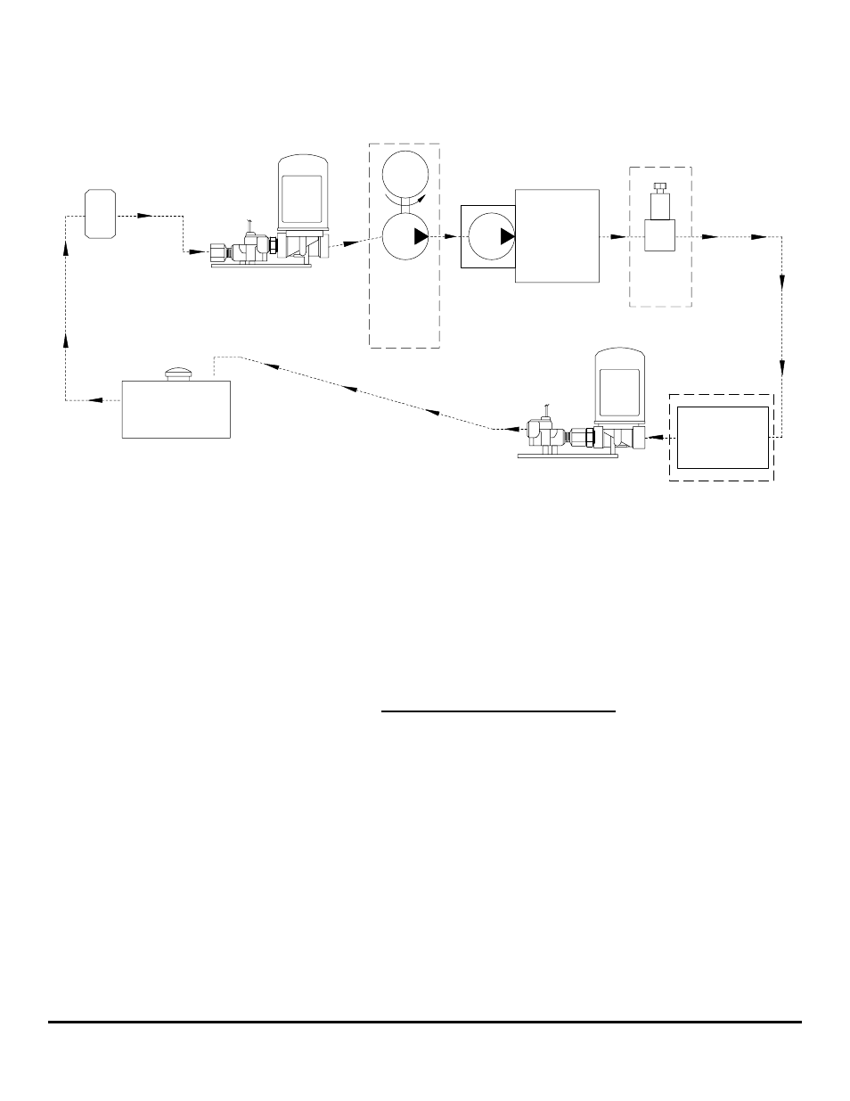
Fuel Flow Schematic - Standard Flow Diesel Systems (BOS, 201, 231 & 235-2K)
Tank
Filter
Forward Sensor
And Pulsation
Damper Assembly
FloScan
Primary
THE RETURN FLOW SENSOR MUST
REMAIN FLOODED AT ALL TIMES.
PLEASE REFER TO STEPS 9-12 BELOW.
Return Fuel
Cooler
(If Used)
The Return Flow Sensor must be installed downstream
of all Pressure Regulators and Fuel Coolers (if used).
The Forward Flow Sensor must be
installed downstream of the Primary Filter
and upstream of all fuel delivery pumps.
Pressure
Regulator
(If Used)
ENGINE
M
Engine-
Mounted
Lift
Pump
Off-Engine
Boost or
Priming
Pump
(If Used)
Return Sensor
And Pulsation
Damper Assembly
FloScan
*Caution: Diesel System Components are not designed for use on Gasoline Fuel Systems.
FloScan Sensor & Pulsation Damper Plumbing Guidelines:
1. Before installing the assembled Flow Sensor & Pulsation Damper assembly’s into the fuel system, verify that their orientation
arrows are pointing UP Ï.
2. The Forward Flow Sensor / Pulsation Damper assembly must be protected by and installed downstream of a 10 to 30 Micron
Primary Filter. The forward assembly can be installed at any convenient location from the bottom of the bilge to the top of the
overhead.
3. NOTE: Always use the primary filter micron rating Specified by the Engine Manufacturer, (usually 10, 20 or 30). Do not
follow advice given by local experts, mechanics, or magazines. There are several reasons for avoiding 2 and 5 micron filters.
4. Filtered fuel must enter into the Forward Sensor through its Hex Flow Straightener on the port marked IN. Fuel must exit through
the Pulsation Damper port with an outward pointing arrow, (Î).
5. Return fuel from the engine, must enter into the Return Pulsation Damper’s inlet port. This is the port marked with an inward
pointing arrow, (Í) and exit through the port marked OUT on the Return Sensor.
6. Install the Forward & Return Sensor – Pulsation Damper assemblies as far from the engine as practical. Maximizing fuel line
length, between the engine and Sensor – Pulsation Damper assembly, improves instrument accuracy.
7. Use the smallest approved fuel line diameter for your engine, especially on the return line. Higher fuel flow velocities increase
overall system accuracy. Refer to the engine owners or shop manual for more information.
8. IMPORTANT NOTE: THE RETURN FLOW SENSOR MUST REMAIN FLOODED AT ALL TIMES.
(Continued on next page)
FloScan Instrument Company, Inc.
Tel:
(206)
524-6625
Fax:
(206)
523-4961
3016 NE Blakeley Street, Seattle, WA 98105
Email:
Http://www.floscan.com
- N20D-201-2K FloNET N20D-BOS-2K FloNET N20RBBOS-2K FloNET N20D0-2012K FloNET N20D-231-2K FloNET N20D0-BOS2K FloNET N20D0-2312K FloNET N20RB201-2K FloNET N2TD-235-2K FloNET FloNET Hi Capacity Flow Model N2TD-6DB-2K FloNET N20D-3CB-2K FloNET N2TD-6DC-2K FloNET N2TD-6DD-2K FloNET N2TRB6DB-2K FloNET N20RB3CB-2K FloNET N2TD-6CB-2K FloNET N2TRB6CB-2K FloNET N2TD0-6DD2K FloNET N2TD-6ED-2K FloNET N20D-3BB-2K FloNET N20D0-3EE2K FloNET N20D-3DC-2K FloNET N20D0-3BB2K FloNET N20D0-3CB2K FloNET N2TD0-6CB2K FloNET N2TD0-6ED2K FloNET N2TD-6GG-2K FloNET N2TD-6FD-2K FloNET N20D0-3ED2K FloNET N2TD-6CC-2K FloNET N2TD-6FE-2K FloNET N20D0-3DB2K FloNET N2TD0-6FE2K FloNET N2TD0-6BB2K FloNET N2TD-6BB-2K FloNET N2TD-6EE-2K FloNET