Figure 2 - typical unit configuration – First Co EVBQ (Variable Speed) User Manual
Page 3
EVBQ Fan Coil can be installed for upflow and horizontal-left applications as factory shipped. Units can be installed for
horizontal-right applications with field modifications.
CAUTION:
Extreme caution must be taken that no internal damage will result if screws or holes are drilled
into the cabinet. Failure to follow this CAUTION could result in product or property damage and minor
personal injury.
-- Upflow Installation
Unit must be mounted on a field supplied return plenum that is open or ducted with return air. Only use return-air opening
provided in the bottom of the unit. All return air must pass through the bottom of the unit and A-coil.
(See Figure 2.)
-- Horizontal Installations
Be sure installation complies with all applicable building codes that may require installation of a secondary condensate pan.
The EVBQ Fan Coil unit is factory assembled for horizontal left side down application without any modification required.
1. Arrange support for unit by setting it in or above secondary condensate pan.
2. When suspending unit from ceiling with metal support straps extreme care should be taken that no internal damage
will result if screws are drilled into the cabinet.
CAUTION:
The unit should be leveled in such a way that there is slope toward the condensate drain nipple
to assure positive drainage. Failure to follow this CAUTION could result in product or property damage.
-- Horizontal Right Conversion
To convert unit for horizontal right side down installations:
1. Remove blower and coil panels.
2. Remove angle bracket holding top of horizontal drain pan.
3. Remove horizontal drain pan and A-coil assembly.
4. Flip horizontal drain pan over to right side and reinstall horizontal drain pan and A-coil into cabinet.
5. Secure forward edge of horizontal drain pan with angle bracket.
6. Replace blower and coil panels.
7. Unit should be leveled in such a way that there is slope toward the condensate drain nipple to assure positive
drainage.
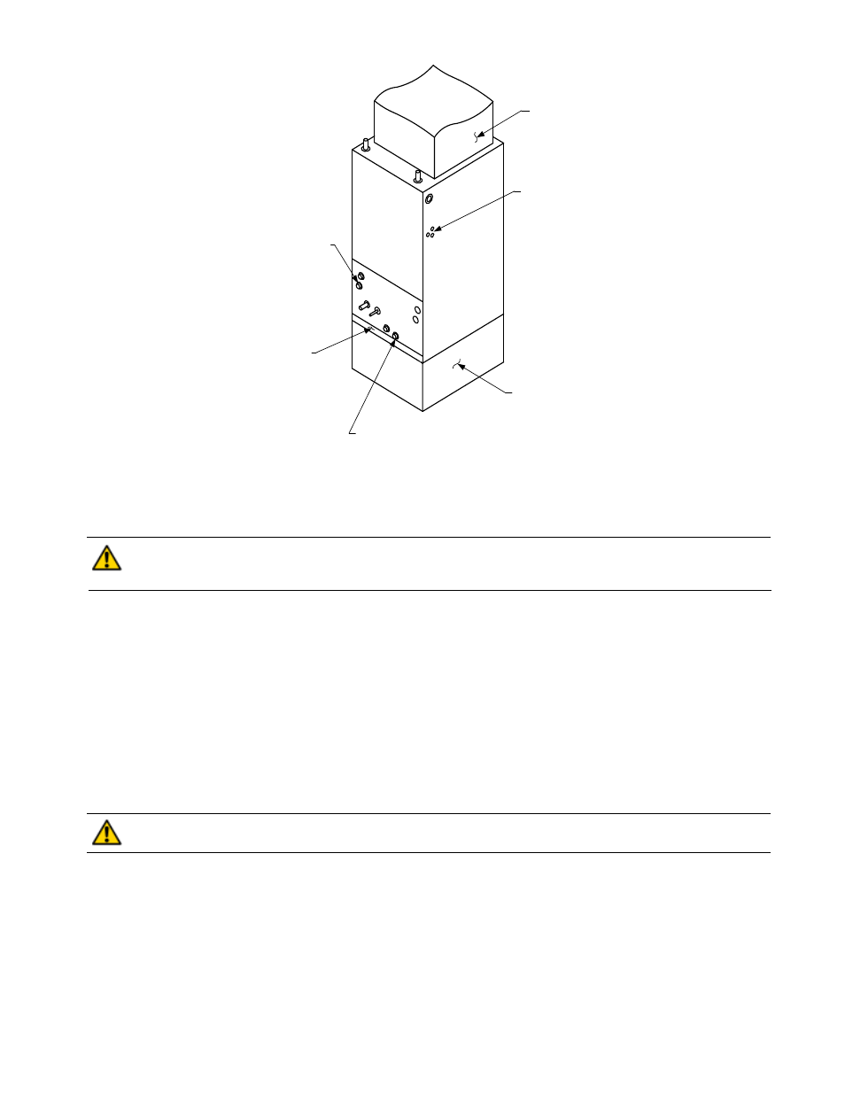
Figure 2 - Typical Unit Configuration
FIELD SUPPLIED
RETURN PLENUM
FIELD SUPPLIED
SUPPLY DUCT
POWER ENTRY OPTIONS
(LOW VOLTAGE ENTRY
OPPOSITE SIDE)
VERTICAL POSITION
CONDENSATE DRAIN
FILTER ACCESS
PANEL
HORIZONTAL POSITION
LEFT SIDE DOWN
CONDENSATE DRAIN
3