0 start up – Electro-Chemical Devices (ECD) HYDRA Ammonium User Manual
Page 26
Page 18
HYDRA NH
4
+
-N
4.0 START UP
The HYDRA Analyzer and Sensor was assembled and tested at the factory before shipment. The sensor
was then disconnected from the analyzer, cleaned and packaged for shipment. The HYDRA C22 analyzer
is configured as shown below and should be ready to use aside from any changes the user may wish to
make to the Outputs, Cleaning Timers and Alarm Set points.
Complete all of the steps in Section 2 INSTALLATION (above) before proceeding further. These steps
include:
1.
Install the Analyzer in a suitable environment.
2.
Determine an installation method and representative sample point for the sensor.
3.
Connect the Air Blast Spray Cleaner tube to a solenoid controlled air supply, 1-4 bar (15-60 psig).
4.
Wire the Power, Outputs, Contact Relays and the HYDRA Sensor to the HYDRA C22 Analyzer.
Familiarize yourself with the MENU Structure of the HYDRA C22 Analyzer, Section 3 (above).
4.1 SET-UP AND CONFIGURATION
The HYDRA C22 analyzer is configured as shown below. Changes to the default configuration can be
easily made as described in Section 3 above.
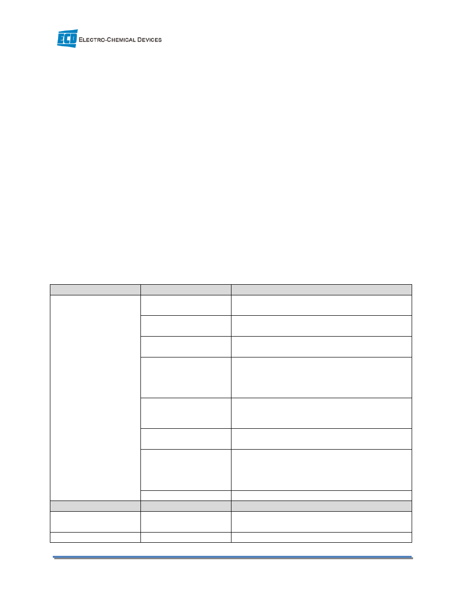
4.1.1 Set Up Menus, Standard
Ch 1 Setup Menu
Settings
Settings
Plot 4-20 1
Sample .1 m
4mA1 0.1 ppb
20mA1 50.00 ppm
2 On > 10.00 ppm
2 Off < 9.500 ppm
Timer 1 : periodic
Per 0d00 :15 :00
Now 0 00 :00 :00
On 0 00 :00 :00
Off 0 00 :00 :30
Timer 2 : oneshot↑
Now 0 00 :00 :00
On 0 00 :00 :00
Off 0 00 :01 :30
Ks 0.10
K+ comp On
TC .333 %/°C
Isopot XXX.X mV
Equilib 9.24 pH
Dissoc 1.000 On
Noise filter 5
Ch 2 Setup Menu
Settings
Settings
TC .333 %/°C
Isopot XXX.X mV
Noise filter 5