DR Power Self-Propelled 6.75 Pro-XL (September 2010 - April 2013) User Manual
Page 28
28
DR
®
TRIMMER/MOWER
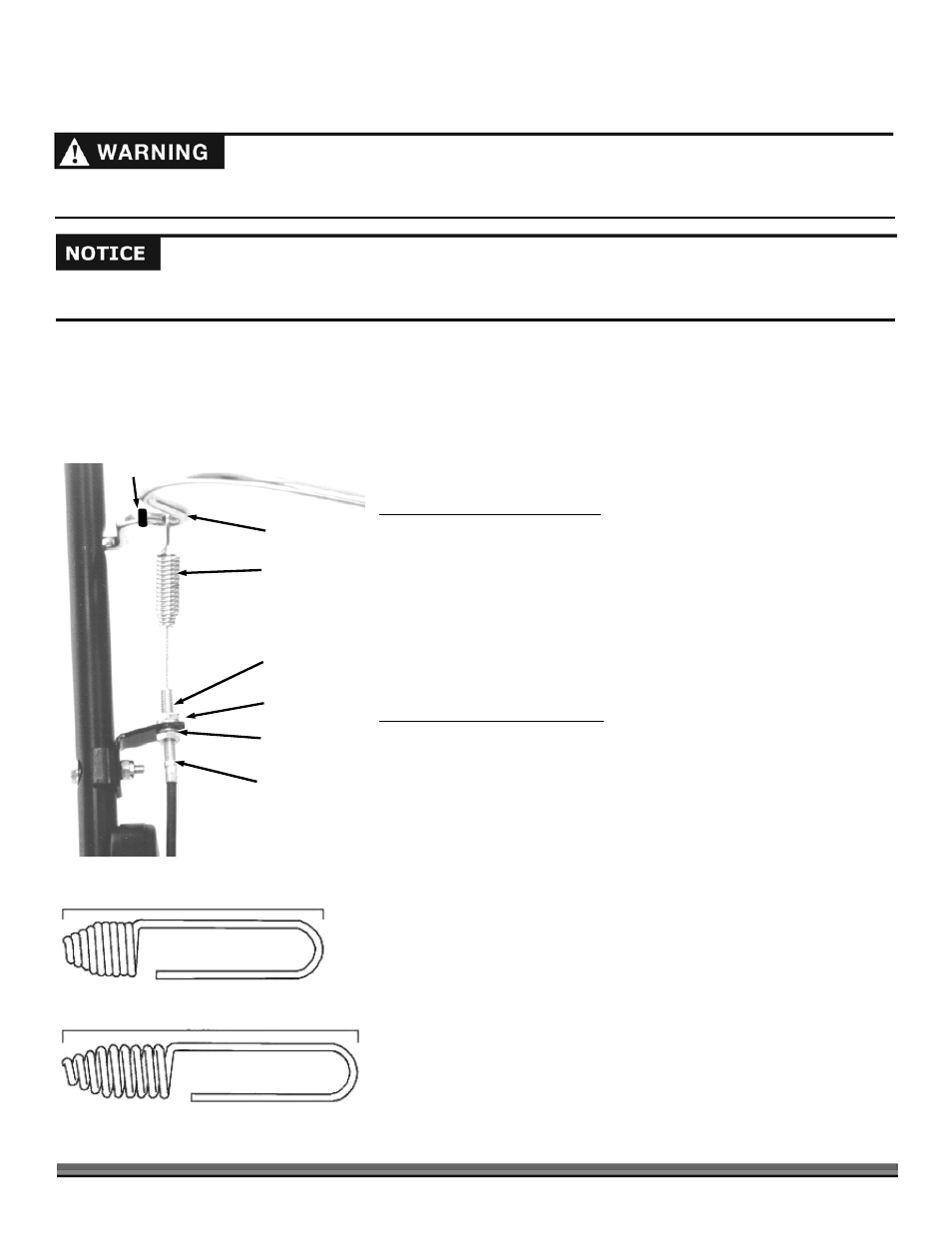
Before adjusting the trimmer control cable, check that the belt mounting is on the correct side of the idler pulleys (see
Figure 34
on page 22), and not frayed, worn or stretched. Also make sure the spring is attached to the bail bar (Figure 46).
Adjusting the Trimmer Head Belt Tension through the Trimmer Control Cable - All models
If the Trimmer Head stops spinning with the Bail Bar engaged and the machine is operating under a heavy load, the Belt may be
too loose. In this case, you may need to adjust the Trimmer Control Cable to put more tension on it. The Adjuster is located on
the right Handlebar, just above the Throttle Control Lever for the SPRINT and PRO models and on the left Handlebar for the
PRO-XL SELF-PROPELLED model.
Tools needed:
Two 1/2" Open-end or Adjustable Wrenches
To increase the tension on the belt:
1. Loosen the upper Control Cable Adjustment Nut, leaving about 1/8" of
space between the Nut and Bracket
(Figure 46).
2. Gently pull down on the Cable as you tighten the lower Nut until it is flush
and snug against the Bracket.
NOTE: If the Trimmer Head still keeps spinning after releasing the Bail Bar, the
Belt may be too tight or the Brake Arm may need replacing. See “Brake Arm” on
page 23.
To decrease the tension on the belt:
1. Repeat the steps for increasing the tension on the Belt, but instead, loosen
the Lower Nut first and then tighten the Upper Nut.
NOTE: To check your adjustment, measure the Spring with the Bail Bar
disengaged. Then measure it with the Bail Bar engaged. There should be a 1/4"
extension in the Spring when the Bail Bar is engaged (Figure 47). Adjust the Nuts
on the Bracket as needed to get the correct measurements.
Before performing any adjustment, maintenance procedure or inspection, stop the engine, wait five (5) minutes to allow parts to
cool and disconnect the spark plug wire, keeping it away from the spark plug.
Bail Bar
Spring
Upper Nut
Bracket
Lower Nut
Metal Cable End
O-Ring
Figure 46
Measure the Bail Bar released
With Bail Bar engaged, should be 1/4" longer
Figure 47