Engaging pta, Returning to normal mode – DR Power Self-Propelled 6.75 Pro-XL (September 2010 - April 2013) User Manual
Page 14
14
DR
®
TRIMMER/MOWER
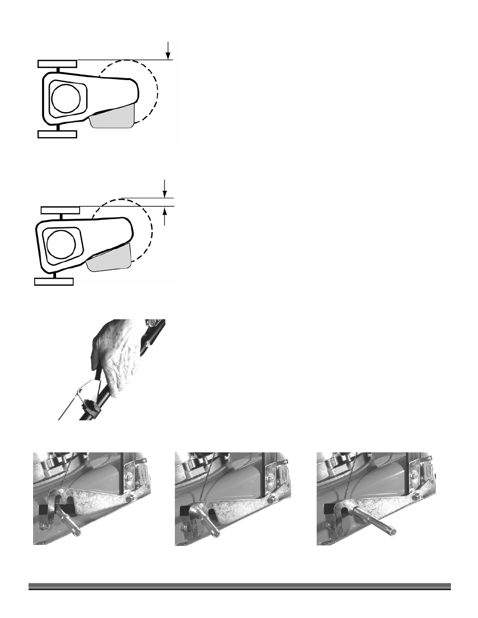
NOTE: In PTA mode, the Trimmer’s Wheels stay straight while the Trimmer
Head tilts (Figure 15). The Cutting Cords extend beyond the wheelbase in the PTA
mode, allowing you to easily cut under obstacles. The Trimmer Head and the
Cutting Cords also tilt slightly in PTA mode so you can edge and trim along
gardens, paths, and driveways. When using PTA along garden edges, fences, and
buildings, we recommend making your first pass with the DR TRIMMER/MOWER
in the Normal mowing position, staying 4 to 8 inches from the obstacle; and then
return for another pass with the machine in PTA mode.
Engaging PTA
®
1. Stand in the Operator’s position.
2. Pull the PTA Lever (Figure 16) against the Handlebar and hold it there.
This unlocks the Axle (Figure 17).
NOTE: Figure 17 shows the Axle with the Wheel removed for clarity.
3. Push down on the Handlebar to tip the nose of the machine a few inches off
the ground. Balancing the weight of the machine on the Wheels makes it
easier to pivot the front of the Trimmer to the left.
4. While continuing to hold the PTA Lever down, grip the sides of the
Handlebar while pulling up with the right hand and pushing down with the
left, swinging the front of the Trimmer to the left.
5. Release the PTA Lever. This will lock the Axle in PTA mode (Figure 17).
Returning to Normal Mode
1. Pull the PTA Lever (Figure 16) against the Handlebar and hold it there.
2. Push down on the Handlebar to tip the nose of the machine up a few inches
off the ground.
3. While continuing to hold the PTA Lever down, grip the sides of the
Handlebar while pulling up with the left hand and pushing down with the
right, swinging the front of the Trimmer to the right, and stopping at center.
4. Release the PTA Lever. This locks the Axle in the Normal operation mode
(Figure 17).
Figure 16
Normal Mode
PTA
Mode
Cords
Extended
Figure 15
PTA
Lever Unlocked
PTA
Lever locked in PTA
PTA
Lever locked in Normal Mode
Figure 17