Replacing the drive belt – DR Power 3-Point Hitch (April 2015 - Present) User Manual
Page 19
CONTACT US AT www.DRpower.com 19
Always make sure you remove the screwdriver from the head assembly when
finished. Failure to remove the screwdriver could cause injury when the head
assembly is engaged.
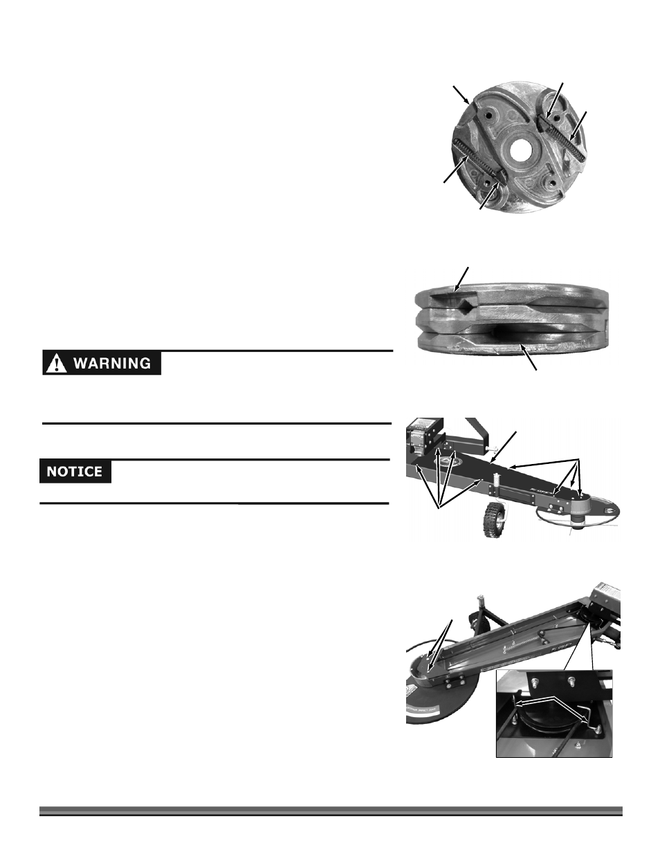
17. Remove the Springs and Locking Cams from the Middle and Bottom Plates
and clean any grass or debris from the Springs and Cams.
18. Clean all Plates using a Nylon Brush and clean Rag to remove all grass and
dirt.
19. Inspect the Springs and Cams for damage. If any parts are damaged please
call DR Power to order a replacement assembly.
20. Reinstall the Springs and Locking Cams into the middle and bottom Plates
(Figure 34).
Note: The Bottom Plate has threaded holes and the middle Plate has clearance
holes. The Plates must be in the correct order for proper assembly.
21. Assemble the Plates ensuring that they are aligned properly and the Springs
and Cams are seated fully into the Plate grooves. The four Screw holes
must be aligned and the two halves of the side cutouts should align from
Plate to Plate (Figure 35).
22. Secure the Cord Head assembly with the four Screws using a 3mm Allen
Wrench.
23. Reinstall the Cord Head as described in the “Replacing the Mow-Ball
®
or
Cord Head” section.
Replacing the Drive Belt
Tools needed:
3/8" Wrench
Two 9/16" Wrenches
9/16" Deep Socket and Ratchet
1. Remove the eight Flange Bolts from the Belt Guard using a 3/8" Wrench
(Figure 36).
2. Lift the Belt Guard from the machine.
3. Remove the two Belt Guide Pins at the head of the Trimmer using two 9/16˝
Wrenches (Figure 37).
Note: Observe the orientation of the Belt Guides in the next step. They must be
positioned in this way when reinstalled.
4. Loosen the two Belt Guides of the Gearbox Pulley using two 9/16˝ Wrenches
and rotate them out of the way.
Figure 36
Belt Guard
Flange Bolts
Flange
Bolts
Use only DR belts on your machine. Do not use hardware store variety belts.
Spring
Figure 34
Locking
Cam
Plate
Spring
Locking
Cam
Outlet Cutout
Figure 35
Inlet Cutout
Belt
Guide
Pins
Figure 37
Belt
Guides