Installing trimmer cords – DR Power 3-Point Hitch (April 2015 - Present) User Manual
Page 11
CONTACT US AT www.DRpower.com 11
3. Align the Key Slot of the PTO Shaft with the Key in the Shaft and slide it
onto the Shaft (Figure 16).
Note: Do not allow the PTO Shaft to contact the Gearbox. The Gearbox Shaft end
should be flush with the inside of the U-Joint.
4. Secure the PTO Shaft by tightening the Set Screw with a 4mm Allen Wrench.
Note: If you plan to leave the Trimmer attached to the Tractor for extended periods,
apply thread lock to the Set Screw to help secure it in place.
5. Push in the Spring Pin at the end of the PTO Shaft and slide it onto the
Tractor Spline (Figure 17). When the PTO Shaft is started on the Tractor
Spline Shaft, release the Pin and continue to push the PTO Shaft until the
Spring Pin locks into the Groove of the Tractor Spline.
6. Attach the Safety Chain of the PTO Shaft around a solid area of the 3-Point
Bracket with the Chain ends attached to both ends of the PTO Shaft Guard
(Figure 18). Make sure the Chain has enough slack in the full range of the
Tractor 3-Point Arm travel.
7. Lower the Gearbox Guard and install the front Bolt, Washers and Locknut
with two 11/16" Wrenches (Figure 19).
8. Tighten the rear Gearbox Guard hardware with two 11/16" Wrenches.
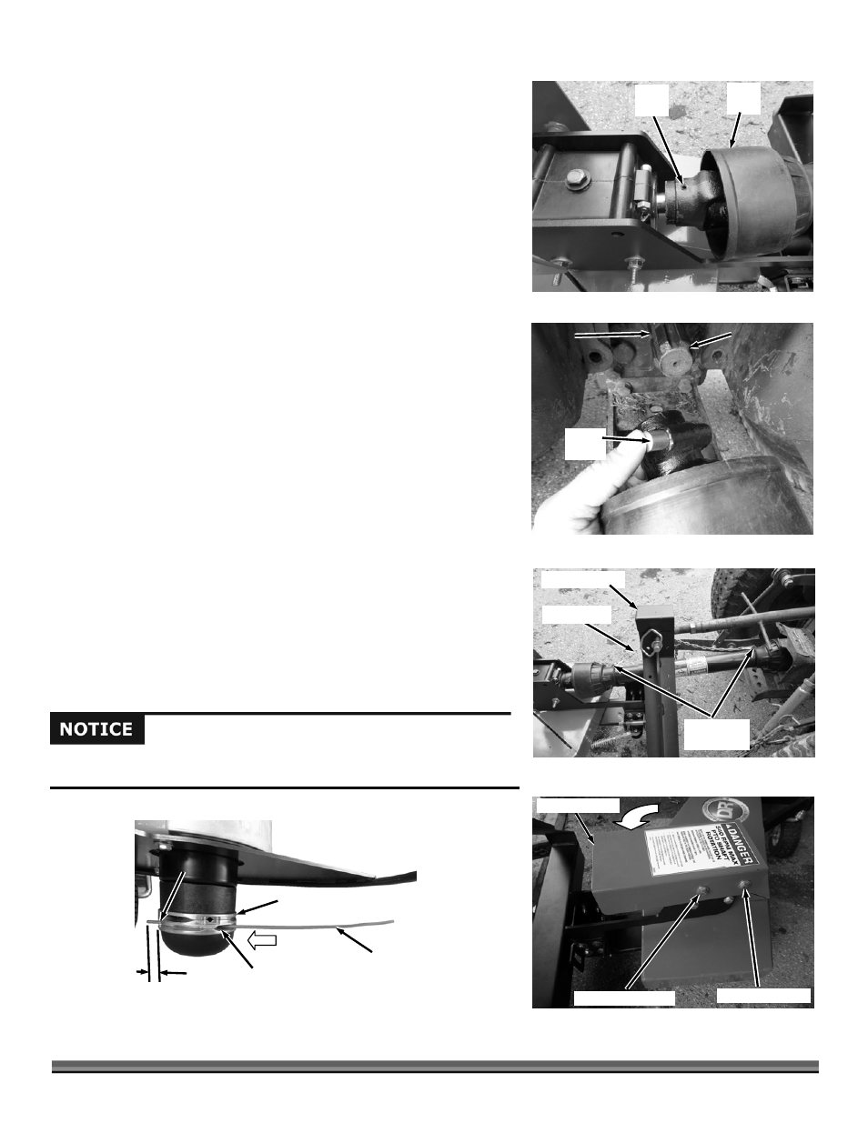
Installing Trimmer Cords
Note: Cutting height adjustments can be made as you learn the trimming
characteristics of the machine in the “Operating the DR 3-Point Hitch
Trimmer/Mower” in the next Chapter.
Always make sure to install all four Trimmer Cords and ensure they are the
same length. Not having all four Cords installed and/or at the same length will
cause excessive vibration and could damage the machine.
1. Insert the end of a Trimmer Cord into the inlet hole (larger slotted cutout)
push it in until the end protrudes out the other side approximately 1/2"
(Figure 20).
2. Turn the Cord Head 90 degrees and repeat the installation until all Cords
are installed.
Note: The Cord can only move through the Cord Head in one direction. To remove
it you must pull it from the other side of the Holder (where the 1/2" end is).
Set
Screw
Figure 16
PTO
Shaft
Gearbox
Tractor Spline
Figure 17
Groove
PTO
Shaft
Spring
Pin
Gearbox Guard
Figure 19
Front Hardware
Rear Hardware
Safety Chain
Figure 18
PTO Guard
Hooks
3-Point Bracket
Trimmer
Cord
Figure 20
Cord Head
Outlet
Approx.
1/2"
Inlet
Running the trimmer without all four cords installed or cords of unequal length
can cause excessive vibration and may damage the machine.