Check the tire pressure – DR Power 42 Lawn Mower Deck User Manual
Page 7
CONTACT US AT www.DRpower.com 7
NOTE: Your Lawn Deck shipped with the Belt in place on the two Blade Drive
Pulleys. Occasionally, the Belt comes off during shipping. If this occurs,
remove the Left and Right Side Belt Covers from the Deck (Figures 6) with
a 1/2" Wrench and place the Belt back on the Pulleys.
1. Remove the Front Knob and the Main Belt Cover (Figures 6).
2. With the help of another person to steady the DR Field and Brush Mower
Power Unit, line up the Lawn Mower Deck with the Power Unit Attachment
Pin and slide the Lawn Mower Deck onto the Pin.
3. Attach the Collar and insert the Retaining Pin (Figure 7).
4. Mount the Belt on the Field and Brush Mower Engine Pulley. Ensure that the
Belt is routed correctly around the other Pulleys (Figure 8).
5. Push the Belt Tension Release Lever towards the center of the Deck and set
the outside of the Belt against the flat Idler Pulley that is on the Release
Lever.
Tip: Some people push the Lever with their foot.
6. Replace the Main and Side Belt Covers if you removed them.
NOTE: Be certain to replace the Side Belt Cover Hardware in the position and order
that you removed it (see “Schematic – Deck Assembly” in Chapter 6 for
reference when re-installing the covers).
Check the Tire Pressure
Tools Needed:
•
Tire Pressure Gauge
•
Air Compressor
1. Remove the Valve Stem Protective Cap and check the tire pressure with a
Tire Pressure Gauge.
2. Refer to the manufacturers recommended pressure is that is stamped on the
side of the Tire.
3. If the pressure is too low, add air through the Valve Stem with an air hose.
4. Replace the Valve Stem Protective Cap when finished.
Do not over inflate the tires. Inflate to the manufacturers recommended
pressure found on the tires.
Main Belt
Cover
Figure 6
Knob
Right Side
Belt Cover
Right Side
Belt Cover
Collar
Figure 7
Retaining
Pin
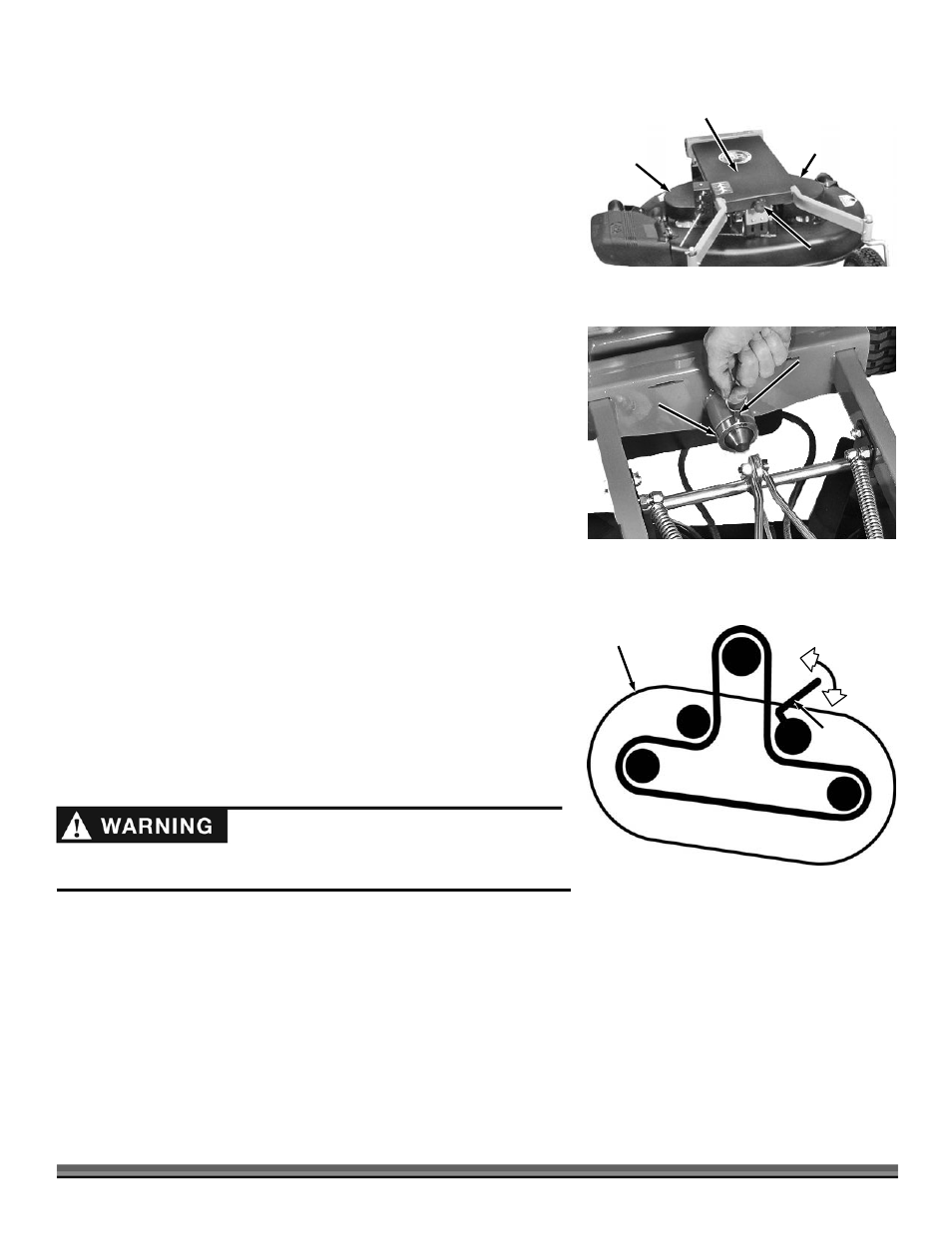
BELT PATH
Engine Pulley
Deck
Belt
Tension
Lever
Apply
Tension
Release
Tension
Figure 8