Installation, Connection diagram – DNF Controls TBC-2-DVC User Manual
Page 4
4
TBC-2 DVC
3. INSTALLATION
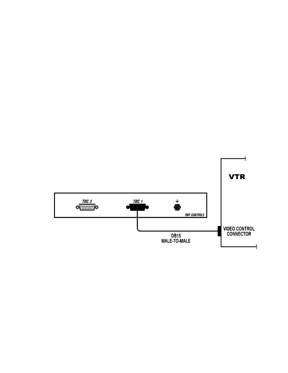
Connect one end of a D-sub15 cable to the TBC 2. Connect the other end of the cable to the
D-sub 15 on the VTR to be controlled. Identified as “Encoder Remote” or “Video Control.”
Because the TBC Remote connector has power on its pins, cabling should be done only with the
VTR power switch turned off. Once the TBC-2 panel is securely connected to the VTR, power
may be safely turned on.
Installation is Complete
CONNECTION DIAGRAM
See also other documents in the category DNF Controls Equipment:
- 2034CL-N (30 pages)
- 4000CL-O V3.1 (32 pages)
- 2034CL-N-PBIO (33 pages)
- 2034CL-TO (24 pages)
- 4000CL-Q (22 pages)
- 2034CL-TO-PBIO (27 pages)
- 2034CL-SX-PBIO (21 pages)
- 4000CL-SX (26 pages)
- 2034CL-MAV (22 pages)
- 2034CL-MAV-PBIO (23 pages)
- 2034CL-L Vs.3.0 (26 pages)
- 2034CL-L-PBIO VS.3.0 (28 pages)
- 4040CL_(-A, -L, -O, -NX, -7, -8, -T, -P) (43 pages)
- 2044CL-L-8 (27 pages)
- 2MCE (19 pages)
- 3040P-L_&_3040P-L-LT (20 pages)
- 3040P-L_&_3040P-L-LT (27 pages)
- 4000CL-LPH (16 pages)
- 3040P-DLO-L (39 pages)
- 4000CL-L-KBIO Vs.3.0 (21 pages)
- 4000CL-MAV70 (14 pages)
- 4000CL-N (25 pages)
- 4000CL-MAV (18 pages)
- 4000CL-TO (21 pages)
- 4000CL-AX (13 pages)
- 4040CL-EVS-PBIO (26 pages)
- Analyst, RS422/RS232 Tester (35 pages)
- Analyst, RS422/RS232 Tester with (LOG 2) VTR Data Logging Option (31 pages)
- USP3-SBX-VSS (10 pages)
- ST100-CP (6 pages)
- AnyWhere Interface Switch (20 pages)
- ST420-CP (11 pages)
- ST300-CP (13 pages)
- GTP-32 (47 pages)
- ST400-CP (19 pages)
- PBUS G and V Command Addendum (2 pages)
- CP20 (42 pages)
- DC21 (29 pages)
- DMAT-O-22 (27 pages)
- DMAT-EZ (26 pages)
- DMAT-DL (19 pages)
- DMAT-MAV (29 pages)
- DMAT-O-42 (25 pages)
- GC-32 GPIO Controller (14 pages)
- GTP-32BP Installation (2 pages)