Digi-Star EZ 320 User Manual
Page 21
19
MODEL 320 - Installation Requirements:
Indicator Mounting:
The indicator is easily attached to the Indicator
Mounting Bracket by hooking the top over the
plate and securing the bottom with two (2)
screws (size# 10-24 x 5/8") and nuts.
Power Connection:
Warning!
Always disconnect the indicator power cord
before "jump starting" or fast charging a
battery. Disconnect all indicator leads
before welding on equipment. Failure to do
so can cause surges which will damage the
scale.
The power cable should be connected directly
to a vehicle battery or regulated power supply.
The scale end of the power cable is attached to
the J901 connector located on the bottom
panel of the scale.
Connect the RED wire from the power cable
to +12 VDC and the BLACK wire to
GROUND. The indicator is fused internally at
4 amps.
POWER CABLE CONNECTIONS
WIRE COLOR
WIRE FUNCTION
RED
BATTERY
(+12 VDC)
BLACK
GROUND
ORANGE
REMOTE ALARM OUT
+
BLUE
REMOTE INPUT
Remote Alarm Connection:
If a remote 12 VDC alarm is to be used,
connect the +12 VDC side of the alarm
to the power cable ORANGE wire and the
GROUND side of the alarm to the frame.
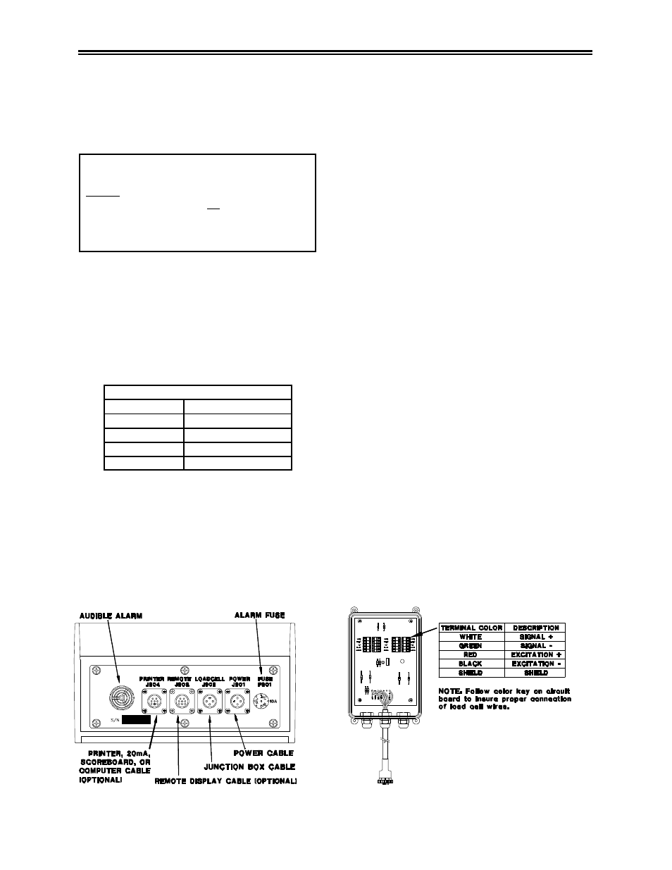
I
NDICATOR
B
OTTOM
P
ANEL
C
ABLE
C
ONNECTIONS
:
The alarm output is fused for a maximum
drain of 10 amps. The remote alarm
connection may also be used for motor
control purposes when used with a relay.
Remote Input Connection:
If the remote input is to be used, connect one
side of the normally open momentary switch
or relay contact to the power cable BLUE
wire, and the other side to the frame or other
GROUND connection. If your power cable
does not contain a blue wire and you desire to
use this feature, contact your dealer for a
special cable. A process control box is
available for motor control and remote enter
preset capability.
Load Cell Connection:
The indicator operates with strain gage load
cells. The system is normally supplied with a
"J-BOX" cable going between the scale and
the load cell junction box. Extension Kits are
available from your dealer in various lengths.
To connect the load cells, attach the junction
box cable to the J902 connector on the
bottom panel of the scale. Connect the load
cell cables to the junction box as shown
below.
Lightning Protection:
Additional protection is achieved with the
proper installation of grounding rods. Please
call (920) 563-9700 request Digi-Star Form
F3050.
J
UNCTION
B
OX
L
OAD
C
ELL
C
ABLE
C
ONNECTIONS
: