48 prl instruction 5, Preparing the mount to receive the antenna – DH Satellite 3M 1 PC Ant 48 Polar or Fixed Series User Manual
Page 5
PREPARING THE MOUNT TO RECEIVE THE ANTENNA
It is time to install the antenna to the mount. You must first elevate the ring to about 60 degrees. Lock it in
place. Locate the 1/8" pilot holes; one is located next to one of the 8- 1/2" holes in the dish and the other is
found on one of the 8 tabs on the mount next to the 1/2" holes. When you have located these two holes you
will need 3-4 people to help pickup the dish and set it into the ring making sure the pilot holes line up. Slip
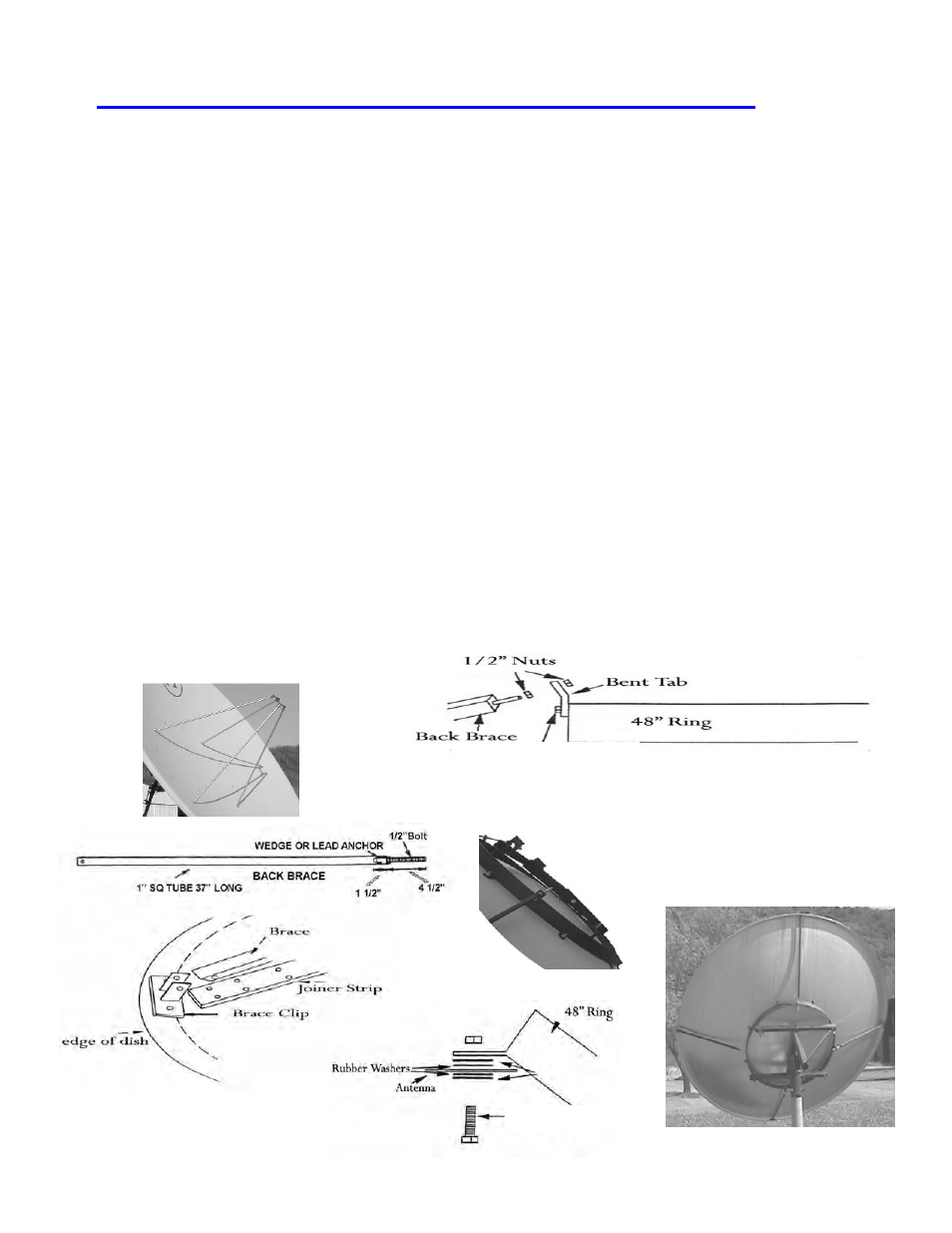
in the l/2"x 1 1/2" bolts using both a rubber & steel washer, leaving out every other bolt until the feed struts
are in place. (see Fig.#1A) Do not tighten these bolts more than just snug. The feed struts should now be
installed. Finish installing the remaining bolts, washers, and nuts to complete the assembly of the antenna
to the ring mount. (Fig.#1 & Fig.#1A) Please read page 6 & 7 “Preparing the feed”.
You are ready to put the dish in a vertical position and use a ladder to assemble and install the feed horn.
Install the bolts as in page 7, Fig.#3 for Ku band. DO NOT OVER TIGHTEN.
Install the back braces finger tight. Refer to drawings #2, #2A, #3, & #4 below
.
There are four holes around the rear of the 48" ring to accept the braces. See Fig.#3. The angle clip( bent
tab, (Fig.#2) is a piece of steel, bent in the middle approximately 1 l/2"x 3" long with two 1/2" holes. You
will find these in the bolt bag. First fasten the clip with 1/2" bolts to the 48" ring; now thread one 1/2" nut
about 2/3rds of the way down on the 1/2" rod end of the brace. Slip the rod end through the clip and install
another 1/2" nut. Only tighten these finger tight. Now, go to the edge of the dish and place the two 1/4" x
3/4" bolts thru the predrilled holes in the lip (Refer to Fi
g. #4)
of the dish and into the end of the brace and
tighten with 1/4" nuts. Repeat this for all four braces.
Set the dish in its normal position for tracking the
arc and walk 30 feet away and sight the front surface of the dish. It should be flat. If it is not, adjust any
brace that may be holding pressure and try to make the front surface flat. Try to do very little adjusting and
try to release pressure to make the antenna as flat as possible
Page 5
Figure #2
Figure #3
Figure #1
Figure #4
Fig.#1A
Back braces are measured
by tube length only. 37” for
36” f/l and 34” for 48” f/l.
Fig.#2A
1/2” x 1 1/2" Bolt
1/2” x 3” Bolt