DFI SR100-N User Manual
Page 31
31
2
Hardware Installation
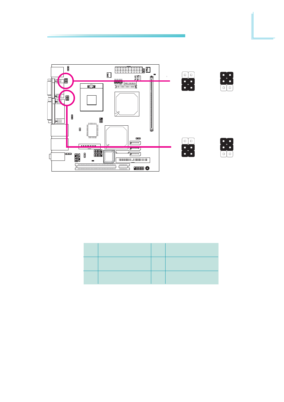
COM 1 and COM 2 are RS-232 por ts. If the serial device
connected to COM 1 and/or COM 2 requires 5V/12V power from
the system board, set JP11 and/or JP13 pins 3-5 (5V) and 4-6
(12V) to On. Otherwise, leave the jumper’s setting at 1-3, 2-4 On.
The table below shows the pin assignment of JP11 and JP13.
1
3
5
MRIX-
X_MRIX-
+5V
2
4
6
MDCDX-
X_MDCDX-
+12V
COM 1 and COM 2 RS232/AUX Select
X
COM 1
JP11
X
COM 2
JP13
4
2
6
3-5 (5V),
4-6 (12V) On:
Auxiliary power
1-3, 2-4 On:
RS232
(default)
3
1
4
5
2
6
COM 1 settings
3
1
5
COM 2 settings
4
2
6
3-5 (5V),
4-6 (12V) On:
Auxiliary power
1-3, 2-4 On:
RS232
(default)
3
1
4
5
2
6
3
1
5
See also other documents in the category DFI Motherboard:
- AR100-DR (112 pages)
- G7B630-N (127 pages)
- G7B630-N (154 pages)
- BT100 (71 pages)
- HR100-CRM (170 pages)
- BT103 (72 pages)
- BT161 (71 pages)
- CM100-C (70 pages)
- CD101-N (69 pages)
- CD102 Series (76 pages)
- CP100-NRM (150 pages)
- CR101-D (67 pages)
- CR100-CRM (177 pages)
- EL339-B (109 pages)
- G5C100-NR (160 pages)
- HD100-H81 (79 pages)
- HD101-H81 (83 pages)
- HD173-H81 (70 pages)
- HM100-QM87 (97 pages)
- HM103-QM87 (99 pages)
- HU103 (95 pages)
- KB161 (68 pages)
- HU173 (90 pages)
- LR100-N18M/N18S (126 pages)
- LR102-B18M (138 pages)
- EL630-NR (149 pages)
- NP101-D16C (150 pages)
- SB102-D (60 pages)
- NP102-N16C (144 pages)
- MB630-CRM (171 pages)
- SB630-CRM (184 pages)
- SB630-CRM (183 pages)
- SR100-L20C (144 pages)
- LT600-L (149 pages)
- G7B630-N (147 pages)
- CA331-P (131 pages)
- EL330-DR (142 pages)
- CP337-NRM (174 pages)
- HD310-Q87 (101 pages)
- EL620-C (192 pages)
- G7L630-B (133 pages)
- HD330-H81 (81 pages)
- HD330-Q87 (85 pages)
- HD332-H81 (76 pages)