Chapter 2 – DFI HM101-HM86 User Manual
Page 26
www.dfi .com
26
Chapter 2 Hardware Installation
Chapter 2
LPC Connector
Pins
Pin Assignment
Pins
Pin Assignment
1
CLK
2
LAD1
3
RST#
4
LAD0
5
FRAME#
6
VCC_+3V
7
LAD3
8
GND
9
LAD2
10
x
11
SERIRQ
12
48MHz
The LPC connector is used to connect an extension module for additional COM/Parallel ports.
The table shown below indicates the pin fuctions of the LPC connector.
Note:
To support the additional COM/Parallel ports, please contact your sales representative
for the LPC module and its BIOS.
12
11
LPC
2
1
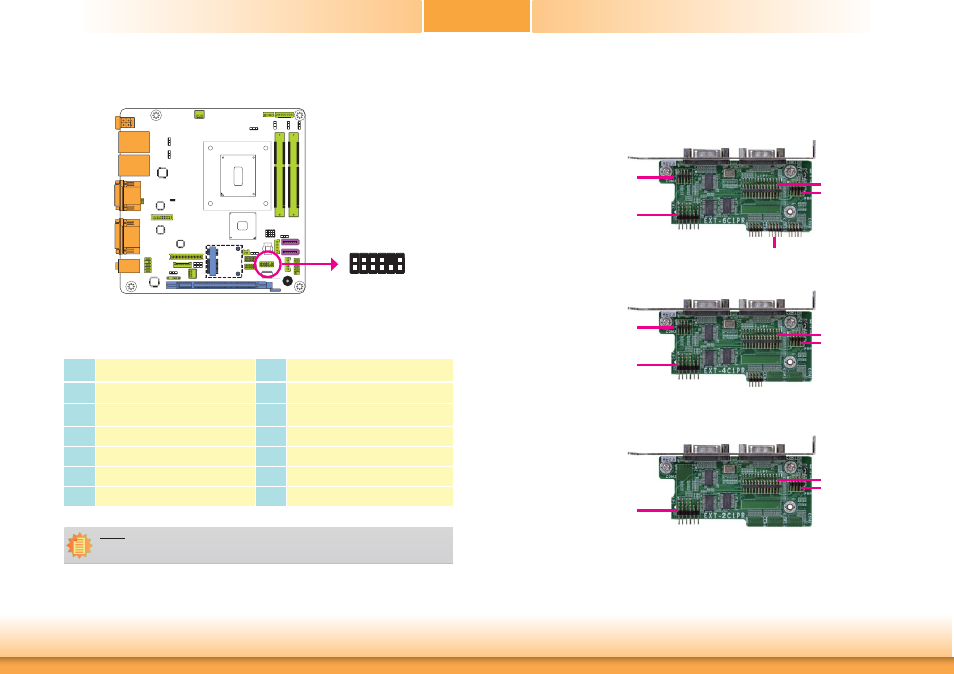
COM/Parallel Extension Modules
There are 3 extension modules supporting additional COM/Parallel ports via the LPC connector.
EXT-6C1PR
6 RS232 COM ports
1 Parallel port
EXT-4C1PR
4 RS232 COM ports
1 Parallel port
EXT-2C1PR
2 RS232 COM ports
1 Parallel port
COM4
COM5
COM6
Parallel
Power
COM3
COM1
COM2
LPC
COM4
Parallel
Power
COM3
COM1
COM2
LPC
Parallel
Power
COM1
COM2
LPC