Chapter 2 – DFI HM101-HM86 User Manual
Page 23
www.dfi .com
23
Chapter 2 Hardware Installation
Chapter 2
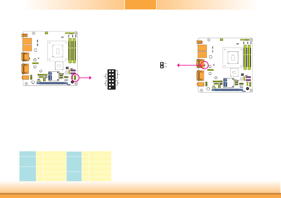
Chassis Intrusion Connector
The board supports the chassis intrusion detection function. Connect the chassis intrusion
sensor cable from the chassis to this connector. When the system’s power is on and a chassis
intrusion occurred, an alarm will sound. When the system’s power is off and a chassis intrusion
occurred, the alarm will sound only when the system restarts.
Chassis
Intrusion
1
2
Ground
Signal
Front Panel Connector
HDD-LED
RESET-SW
PWR-LED
PWR-BTN
11 12
2
1
Front
Panel
HDD-LED - HDD LED
This LED will light when the hard drive is being accessed.
RESET-SW - Reset Switch
This switch allows you to reboot without having to power off the system.
PWR-BTN - Power Switch
This switch is used to power on or off the system.
PWR-LED - Power/Standby LED
When the system’s power is on, this LED will light. When the system is in the S1 (POS - Power
On Suspend) state, it will blink every second. When the system is in the S3 (STR - Suspend To
RAM) state, it will blink every 4 seconds.
Pin Pin Assignment
Pin Pin Assignment
HDD-LED
3
HDD Power
PWR-LED
2
LED Power
5
Signal
4
LED Power
RESET-SW
7
Ground
6
Signal
9
RST Signal
PWR-BTN
8
Ground
11 N.C.
10
Signal