Chapter 2 – DFI HM101-HM86 User Manual
Page 16
www.dfi .com
16
Chapter 2 Hardware Installation
Chapter 2
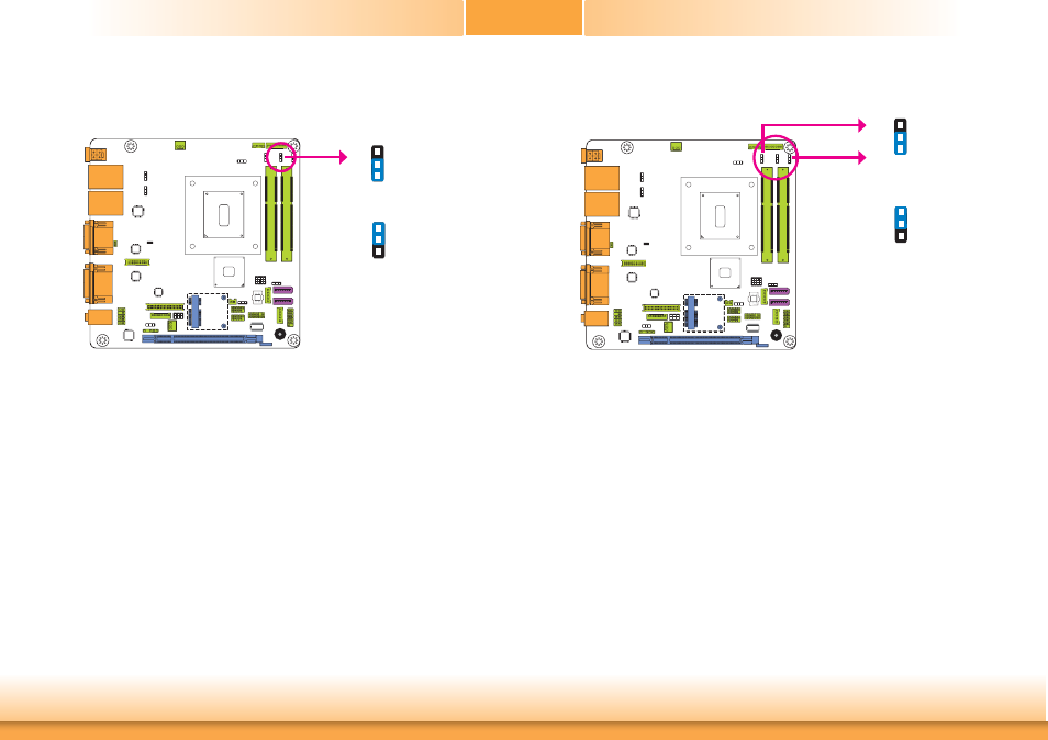
Digital I/O Power Select
2-3 On: +5V
1-2 On: +5V_standby
(default)
JP11 is used to select the power of Digital I/O signal.
1
3
2
1
3
2
Digital I/O Output State
1-2 On: +5V or
+5V_standby
(default)
2-3 On: GND
Based on the power level of DIO (Digital I/O) selected on JP11, JP12 (DIO pin 0-3) andJP9
(DIO pin 4-7) are used to select the output state of Digital I/O: pull high or pull low. When
selecting pull high, the power selection will be the same as the JP11’s setting.
1
3
2
1
3
2
JP11
DIO 0-3
(JP12)
DIO 4-7
(JP9)
This manual is related to the following products: