Chapter 2, S/pdif connector, Power connector – DFI HM100-HM86 User Manual
Page 25
www.dfi .com
25
Chapter 2 Hardware Installation
Chapter 2
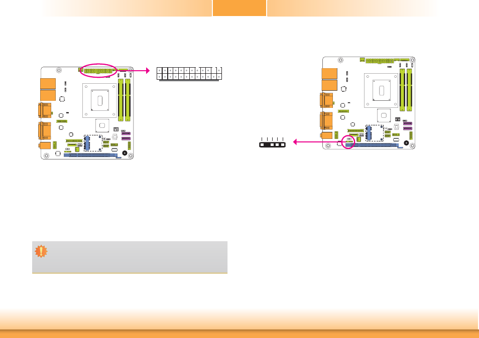
S/PDIF Connector
The S/PDIF connector is used to connect an external S/PDIF port. Your S/PDIF port may be
mounted on a card-edge bracket. Install the card-edge bracket to an available slot at the rear
of the system chassis then connect the audio cable to the S/PDIF connector. Make sure pin 1
of the audio cable is aligned with pin 1 of the S/PDIF connector.
1
5
+5V Ke
y
SPDIF out Ground SPDIF in
S/PDIF
Power Connector
Use a power supply that complies with the ATX12V Power Supply Design Guide Version 1.1.
An ATX12V power supply unit has a standard 24-pin ATX main power connector that must be
inserted into the 24-pin connector.
The power connector from the power supply unit is designed to fit the 24-pin connector in
only one orientation. Make sure to find the proper orientation before plugging the connector.
The system board requires a minimum of 300 Watt power supply to operate. Your system
configuration (CPU power, amount of memory, add-in cards, peripherals, etc.) may exceed the
minimum power requirement. To ensure that adequate power is provided, we strongly recom-
mend that you use a minimum of 400 Watt (or greater) power supply.
Important:
Insufficient power supplied to the system may result in instability or the add-in boards
and peripherals not functioning properly. Calculating the system’s approximate power
usage is important to ensure that the power supply meets the system’s consumption
requirements.
ATX
power
13
12
24
1
+3.3VDC
+3.3VDC
COM
+5VDC
COM
+5VDC
COM
PWR_OK
+5VSB
+12VDC
+12VDC
+3.3VDC
+3.3VDC
-12VDC
COM
PS_ON#
COM
COM
COM
NC
+5VDC
+5VDC
+5VDC
COM