Chapter 2 – DFI HM100-HM86 User Manual
Page 19
www.dfi .com
19
Chapter 2 Hardware Installation
Chapter 2
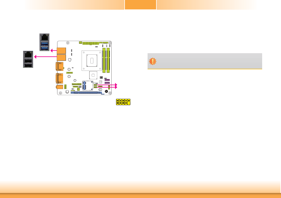
USB Ports
The USB device allows data exchange between your computer and a wide range of simultane-
ously accessible external Plug and Play peripherals.
The system board is equipped with two onboard USB 3.0 ports (USB 0-1) and two onboard
USB 2.0 ports (USB 2-3). The 10-pin connectors allow you to connect 4 additional USB 2.0/1.1
ports (USB 8-9/10-11). The additional USB ports may be mounted on a card-edge bracket.
Install the card-edge bracket to an available slot at the rear of the system chassis and then
insert the USB port cables to a connector.
BIOS Setting
Configure these onboard USB devices in the Advanced menu (“USB Configuration” submenu)
of the BIOS. Refer to the chapter 3 for more information.
Driver Installation
You may need to install the proper drivers in your system operation to use the USB device.
Refer to your operating system’s manual or documentation for more information.
10
VCC -Data
+Data
GND Ke
y
VCC -Data +Data GND N. C.
9
1
2
USB 2.0
USB 3
USB 2
USB 2.0
USB 1
USB 0
USB 3.0
USB 10-11
USB 8-9
Important:
If you are using the Wake-On-USB Keyboard/Mouse function for 2 USB ports, the
+5V_standby power source of your power supply must support ≥1.5A. For 3 or more
USB ports, the +5V_standby power source of your power supply must support ≥2A.
Wake-On-USB Keyboard/Mouse
The Wake-On-USB Keyboard/Mouse function allows you to use a USB keyboard or USB mouse
to wake up a system from the S3 (STR - Suspend To RAM) state. To use this function:
• Jumper
Setting
JP1 and JP2 must be set to “2-3 On: +5V_standby”. Refer to “USB Power Select” in this chap-
ter for more information.