3 venus 1500 control system, Venus 1500 real time, Venus 1500 control system – Daktronics Aquatics Interface with Daktronics Matrix Displays User Manual
Page 19
Daktronics Matrix Displays with Colorado Timing Systems
15
3.3 Venus 1500 Control System
Refer to DWG-604064 and DWG-604462 for general system layouts with the CTS timer and
Hy-Tek connected to a Venus 1500 controlled display.
Venus 1500 Real Time
1. Connect a 9-pin female to a 9-pin
female null modem cable from the
Hy-Tek computer to the Venus 1500
(V1500) computer.
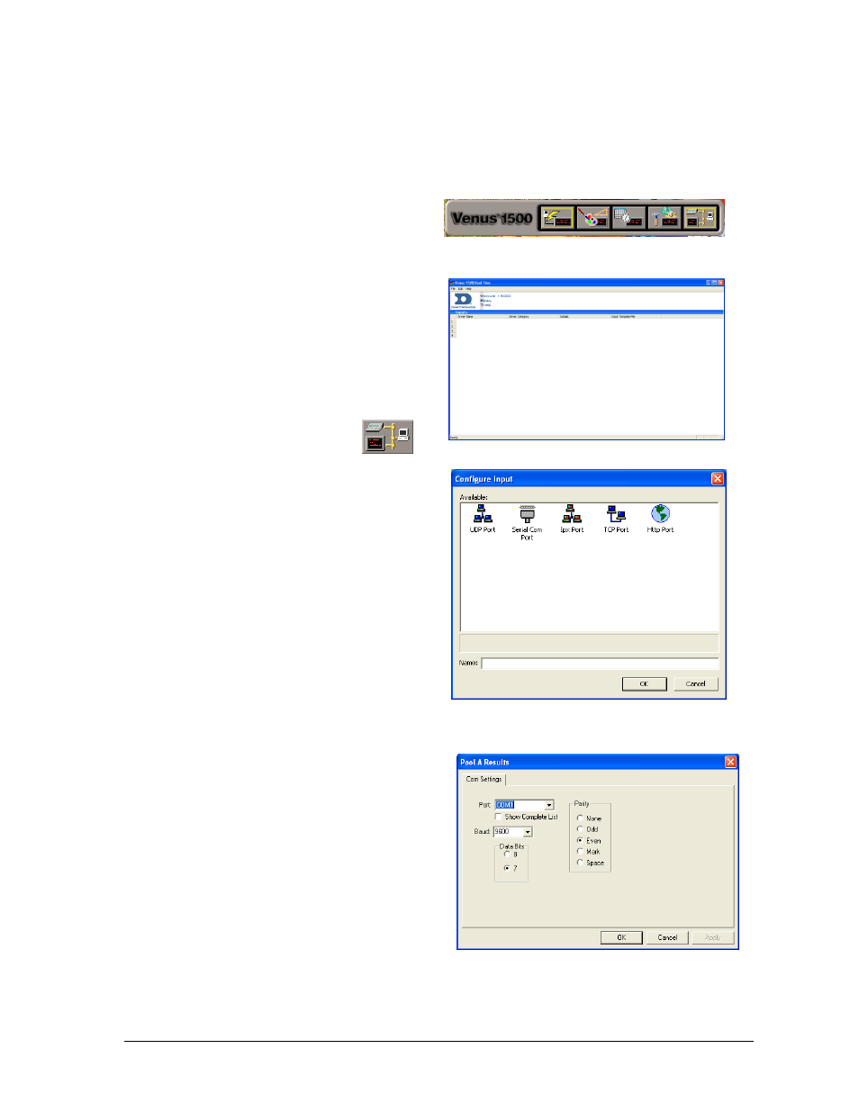
2. Open V1500 Real Time by selecting
V1500 Real Time icon from the
Venus 1500 shell (Figure 27).
Note: If the computer
screen does not display
the Venus 1500 Real Time icon, call
Daktronics to request a USB software
key contact Customer Support. Refer
to Section 6.
The Venus 1500 Real Time Main
screen will appear (Figure 28).
3. Double-click on Input 2 and click
Configure.
4. On the Input Properties screen (Figure
31) click Configure. From the
Configure Input window (Figure 29)
select Serial Com Port and type in a
descriptive name (Ex: “Pool A
Results”) then click OK.
5. Select the Com Port number that the 9-
pin cable is plugged into on the V1500
machine as the port number to edit.
Refer to Figure 30 for the appropriate
Com Port settings, and click OK when
finished.
Figure 27: Venus 1500 Shell
Figure 28: Venus 1500 Real Time
Figure 29: Configure Input
Figure 30: Com Settings