Daktronics Aquatics Interface with Daktronics Matrix Displays User Manual
Page 18
14
Daktronics Matrix Displays with Colorado Timing Systems
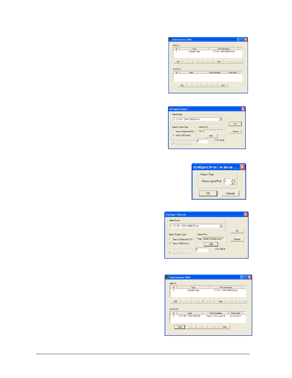
5. After opening the Timer Interface 2000 program
again, click Add under the OUTPUTS: section
(Figure 22).
6. The Configure Output: window will open
Under Select Input: select the previously
configured input to receive the data. (Example:
1:CTS #1 – Com1,9600,8,Even)
Under Select Output Type:, select Venus 7000
Direct then click Edit under Select Port.
7. Select the Venus 7000 RTD input port to send
the data to and click OK (Figure 24).
8. Click OK in the Configure Output: window to
accept the new settings (Figure 25).
9. The note shown in Figure 21 will appear. Click OK. After
configuring an output, shut down the TimerInterface 2000
program and then re-start it for all of the
settings to take effect.
10. The TimerInterface 2000 screen shows each
configured input and output (Figure 26).
For inputs from additional timing consoles,
repeat steps 1-9, naming the next timer input
CTS #2 with the correct Com Port and RTD
input settings. Refer to DWG- 539079.
11. For input settings when connecting a CTS
System 6 to a Galaxy display via Ethernet and
Show Control System, refer to DWG- 1036117.
Figure 22: TimerInterface 2000 with Input
Figure 23: Configure Output:
Figure 24: Select Input
Figure 25: Complete Output Settings
Figure 26: TimerInterface with Input & Output