3 modem system, 4 tcp/ip or lan system, 4 sign to sign connections – Daktronics G-100-7.6-R User Manual
Page 18: 3modem system -4, 4tcp/ip or lan system -4, 4sign to sign connections -4
Electrical Installation
3-4
3. Plug the signal converter’s power cord into a 120 VAC grounded outlet.
4. Plug a flipped phone cable into the “RS/422 OUT” of the signal converter and the
opposite end into the “RS/422 IN” of the first display.
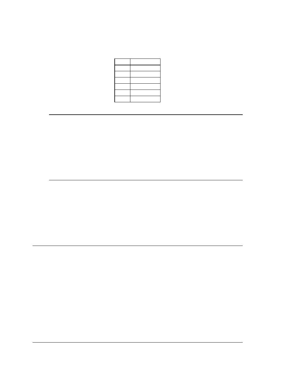
The “RS422 IN” jack’s pin out is as follows:
Pin
Function
1 N.C.
2 D1OUT-P
3 D1OUT-N
4 D1IN-P
5 D1IN-N
6 N.C.
3.3.3 Modem System
Reference Drawing: System Riser Diagram; Modem ......... Drawing A-91386
A modem system uses a standard phone line to connect the computer to the sign. At
the display, simply plug in a phone cable from the J-box into the jack labeled
“PHONE IN” (the plug location is at the same point as shown in Figure 10).
At the PC, hook up the PC modem per the manufacturer’s instructions, then follow
the Venus 1500 manual (ED-12717) to determine the PC modem’s configuration.
3.3.4 TCP/IP or LAN System
Reference Drawing: V1500 System Riser Diagram ............ Drawing A-93904
A LAN system requires a computer running on a LAN.
1. Connect the serial server to the LAN. The server has an RS/232 output just as a
PC would.
2. Follow the steps for setup of a RS/232 system.
3.4
Sign to Sign Connections
Reference Drawings: RS/422 System Riser .................................. Drawing A-91387
RS/232 System Riser .................................. Drawing A-91388
The sign-to-sign connections are the same for the RS/232 system, RS/422 system, modem
system and TCP/IP system. Refer to the riser diagrams at the end of Section 2.
When wiring a sign to sign network, the cable and connectors discussed earlier in this section
are used. Pay special attention to the information regarding flipped cables to help ensure a
successful installation. The best method of wiring the signs together is to start at the first sign,
as it is designated to begin the network.