Daktronics S-100/S-200 User Manual
Page 24
Electrical Installation
3-5
3.4
Computer to Sign
Reference Drawings:
System Riser Diagram; RS/232................................................................Drawing A-91388
System Riser Diagram; RS/422................................................................Drawing A-91387
System Riser Diagram; Modem ................................................................Drawing A-91386
V1500 System Riser Diagram ...................................................................Drawing A-93904
RS232 System
A RS232 system connects the first sign directly
to the computer with an adapter cable. The
adapter cable comes with both a 9 pin and a 25
pin connector. Refer to Drawing A-91388 and
the following steps.
1. Plug the 9-pin or 25-pin connector
(depending on your PC) to the PC’s
RS232 serial COM port.
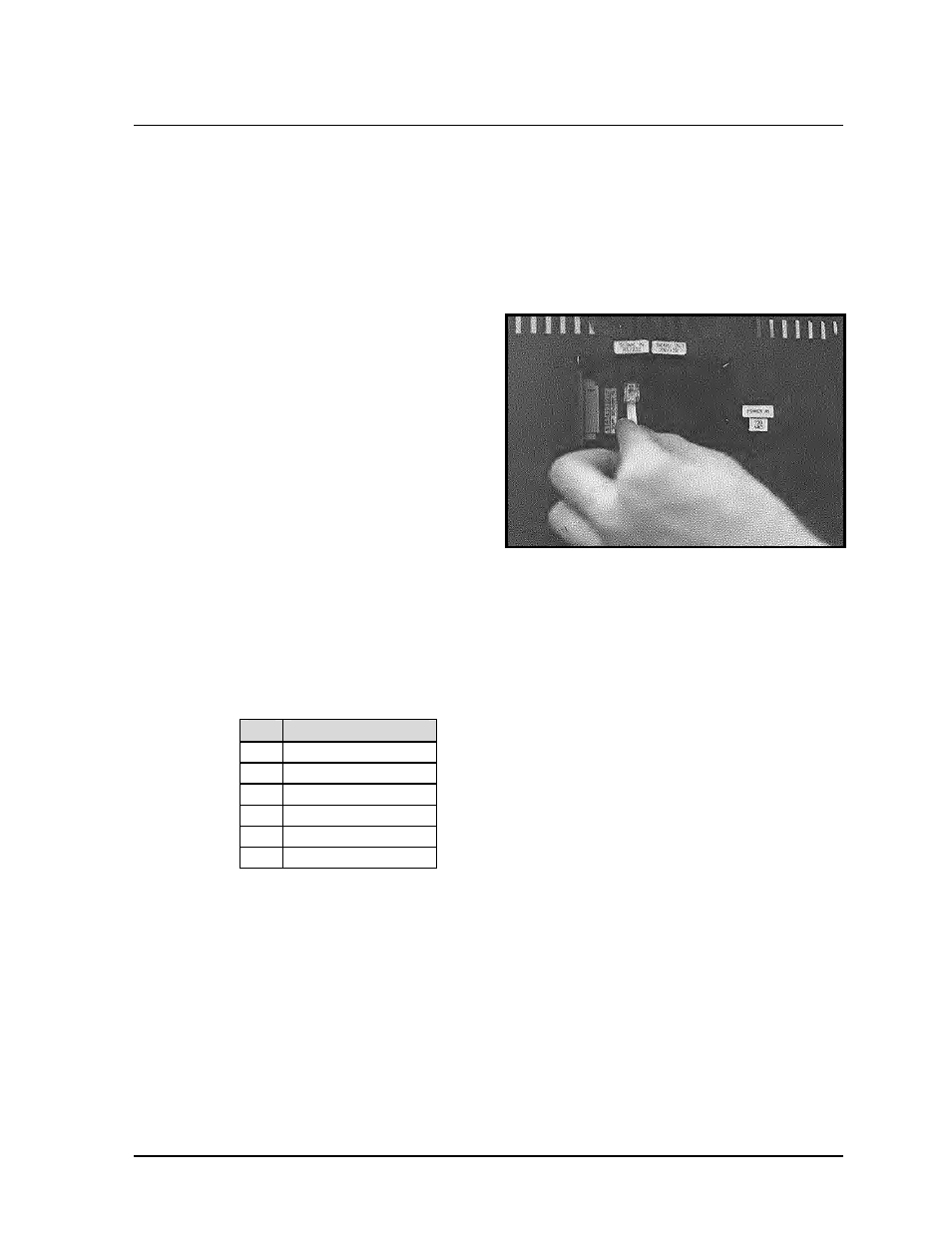
2. Plug one end of the phone cable into
the adapter and the opposite end into
the “RS232 IN” jack on the rear of the
display (refer to Figure 17).
Note: The input connection is applicable for a RS232, RS422, modem or TCP/IP system. The
“SIGNAL IN” label will reflect the correct system.
The “RS232 IN” jack’s pin out is as follows:
Pin Function
1
RTS_OUT-P
2
RESET_OUT-P
3
TX_OUT-N
4
GND-N
5
RS_IN-N
6
DCD_IN-P
RS422 System
A RS422 system requires a signal converter to connect the first sign to the computer. Refer to
Drawing A-91387 and the following steps.
1. Plug the serial cable’s 25-pin connector into the signal converter as shown in Figure
17.
2. Plug either the 9-pin or the 25-pin connector (depending on your PC) into the RS232
COM port to be used.
3. Plug the signal converter’s power cord into a 120 VAC grounded outlet.
4. Plug a flipped phone cable into the “RS422 OUT” of the signal converter and the
opposite end into the “RS422 IN” of the first display.
Figure 17: Input Signal Cable Connection