Daktronics DF-12xx User Manual
Page 39
Maintenance and
4-7
Troubleshooting
In the display, the signal surge
suppression board is an inline
device used to filter the
current loop data line. It
suppresses surges down to a
low voltage to protect the
display’s controller. Refer to
Drawing A-184918 for the
location of the surge board
inside the driver enclosure.
The surge board is pre-wired
before the display is shipped.
Note: The surge suppressor must be firmly connected to the driver enclosure, and
the display must be properly grounded in order to be effective.
Replacing a Modem
Reference Drawings:
Modem Installation; 4 col MASC Driver Enc............................... A-177039
Electrical Specification Drawings............................. Refer to Appendix A
Mechanical Specification Drawings ......................... Refer to Appendix A
If a modem is included with the display, it is mounted inside the display enclosure,
behind a digit, and near the driver but the location and mounting varies by model.
Refer to Drawing A-177039 and the Electrical and Mechanical Specification
Drawings for the location of the modem. All displays in this series are front-
accessible.
1. Open the digit panel or display face panel as
described in Section 4.2.
2. Remove the cover from the driver enclosure.
3. Disconnect all connectors from the modem. Release
each connector by squeezing together the locking
tabs as you pull the connector free. Note: When
reconnecting, remember that these are keyed
connectors and will attach in one way only. Do not
attempt to force the connections.
4. Remove the nuts securing the modem to the inside
of the enclosure.
5. Carefully lift the modem from the display and place
it on a clean, flat surface.
6. Follow the steps in reverse order to attach a new
modem.
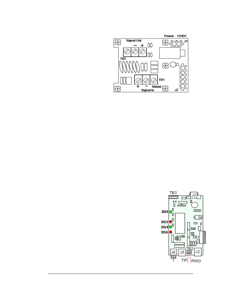
The modem has four LEDs.
Figure 20: Signal Surge Suppression Board
Figure 21: Modem Board