Radio settings, 5 signal connection, Signal connection – Daktronics TN-2601 Outdoor LED Tennis Scoreboard User Manual
Page 26
20
Electrical Installation
Radio Settings
During the POST, the radio channel settings will be
displayed on the scoreboard (Figure 20). When using
the RC-100 controller, the scoreboard will display
“CXX”, where the XX is a channel from 01-15.
Scoreboards that do not show game score will only
display the second digit of the channel number. If an
optional Time of Day clock is installed, the radio
settings will appear there.
For single-court scoreboards using the All Sport 5000
controller, the scoreboard will display “bX CY”
where X is the Broadcast group number and Y is the
Channel number. Scoreboards that do not have game
scores will only display the channel number.
Note: If these settings do not appear, the radio
receiver(s) may need to be repaired/replaced.
The TN-2605 is unable to display radio settings.
These values must match the settings within the console. Refer to the appropriate control
console manual listed in Section 1.1.
3.5 Signal Connection
For scoreboards using a wired setup, route signal
cable through the conduit knockout on the rear of
the scoreboard to the signal surge arrestor card
(Figure 22), located just above the power
termination block in the driver enclosure.
At the SIGNAL IN terminal block, connect red
signal wire to positive (+) and black signal wire to
negative (-).
Note: Be sure to properly connect the shield
(silver) wire to the SHIELD terminal.
For signal cable, Daktronics recommends, as a minimum, single-pair, shielded cable, 22 AWG
(part # W-1077). Two-pair shielded cable (part # W-1234) is preferred. For multi-court
scoreboards using team name message centers (TNMCs), signal installation also requires an
enclosed wireless base station to receive the signal from the handheld RC-100 controllers, a
computer running DakTennis™ software, and signal converters to receive and transmit the
scoring data. Refer to Figure 16 for a typical setup diagram.
Figure 20: RC-100 Radio Settings
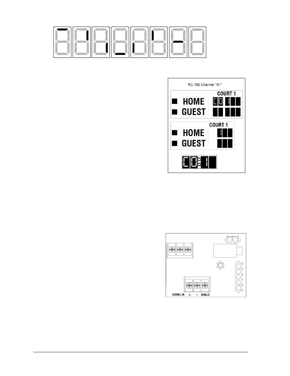
Figure 21: Digit Segment POST
Figure 22: Signal Surge Arrestor Card
- TN-2603 Outdoor LED Tennis Scoreboard TN-2604 Outdoor LED Tennis Scoreboard TN-2605 Outdoor LED Tennis Scoreboard TN-2606 Outdoor LED Tennis Scoreboard TN-2607 Outdoor LED Tennis Scoreboard TN-2650 Outdoor LED Tennis Scoreboard TN-2651 Outdoor LED Tennis Scoreboard TN-2652 Outdoor LED Tennis Scoreboard TN-2653 Outdoor LED Tennis Scoreboard TN-2654 Outdoor LED Tennis Scoreboard TN-2655 Outdoor LED Tennis Scoreboard TN-2656 Outdoor LED Tennis Scoreboard TN-2657 Outdoor LED Tennis Scoreboard P1647 Single-Section Outdoor LED Scoreboard P1647 Multi-Section Outdoor LED Scoreboard FB-2500 Modular LED Football Scoreboard FB-2600 Modular LED Football Scoreboard