Multi-court power connection, 4 power-on self-test (post), Power-on self-test (post) – Daktronics TN-2601 Outdoor LED Tennis Scoreboard User Manual
Page 25
Electrical Installation
19
Note: If a power receptacle is needed to operate the control console at the scoreboard for
troubleshooting, Daktronics recommends that an installation electrician provides a 120 V
outlet close to the disconnect box specifically for this purpose.
Multi-Court Power Connection
Daktronics multi-court tennis
scoreboards have a built-in breaker for
power termination. Refer to the
component location drawings in
Appendix A for precise power/signal
termination location for each model.
1. Route the power cables via
conduit into rear of scoreboard.
2. Look for a warning label similar
to Figure 17 to locate the
appropriate access panel to the
power breaker enclosure.
3. Loosen the screws or latches to
open the access panel.
4. Route the power cables up
through the bottom of the
enclosure.
5. Use a flathead screwdriver to
rotate the two latches
1
/
4
turn, and then remove the
enclosure cover.
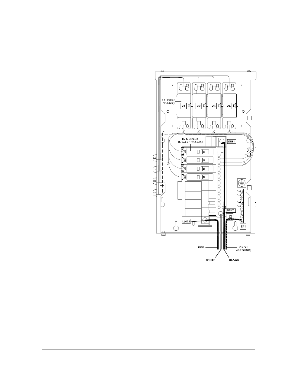
6. Connect the power cables as
follows and shown in Figure 19:
neutral (white) wire to
NEUT.
live wires to LINE 1
(black) and LINE 2 (red)
ground wire
(green/yellow) to the
grounding buss bar, E41
7. Reattach the metal enclosure
cover and secure the access panel.
3.4 Power-On Self-Test (POST)
The scoreboard performs a self-test each time that power is turned on and the control console
is powered off or not attached to the scoreboard. If the control console is attached and
powered on, the self-test does not run, and data from the control console is displayed on the
scoreboard after a brief period of time. Each scoreboard self-test pattern will vary depending
on the scoreboard model, the number of drivers and types of digits. Figure 21 shows an
example of the LED bar test pattern that each digit performs.
Figure 19: Multi-Court Power Termination (120/240 V)
- TN-2603 Outdoor LED Tennis Scoreboard TN-2604 Outdoor LED Tennis Scoreboard TN-2605 Outdoor LED Tennis Scoreboard TN-2606 Outdoor LED Tennis Scoreboard TN-2607 Outdoor LED Tennis Scoreboard TN-2650 Outdoor LED Tennis Scoreboard TN-2651 Outdoor LED Tennis Scoreboard TN-2652 Outdoor LED Tennis Scoreboard TN-2653 Outdoor LED Tennis Scoreboard TN-2654 Outdoor LED Tennis Scoreboard TN-2655 Outdoor LED Tennis Scoreboard TN-2656 Outdoor LED Tennis Scoreboard TN-2657 Outdoor LED Tennis Scoreboard P1647 Single-Section Outdoor LED Scoreboard P1647 Multi-Section Outdoor LED Scoreboard FB-2500 Modular LED Football Scoreboard FB-2600 Modular LED Football Scoreboard