8connectionbetweentheradiatingpanelandth, 9controlandindication, 10interconnection – CREATOR Wireless IR Interpretation System User Manual
Page 22: 11physicalfeatures, 12electricalfeatures
CREATOR CORPORATION (CHINA) 2010-04 WWW.CREATOR1997.COM
15
Digital IR Language Distribution System User Manual
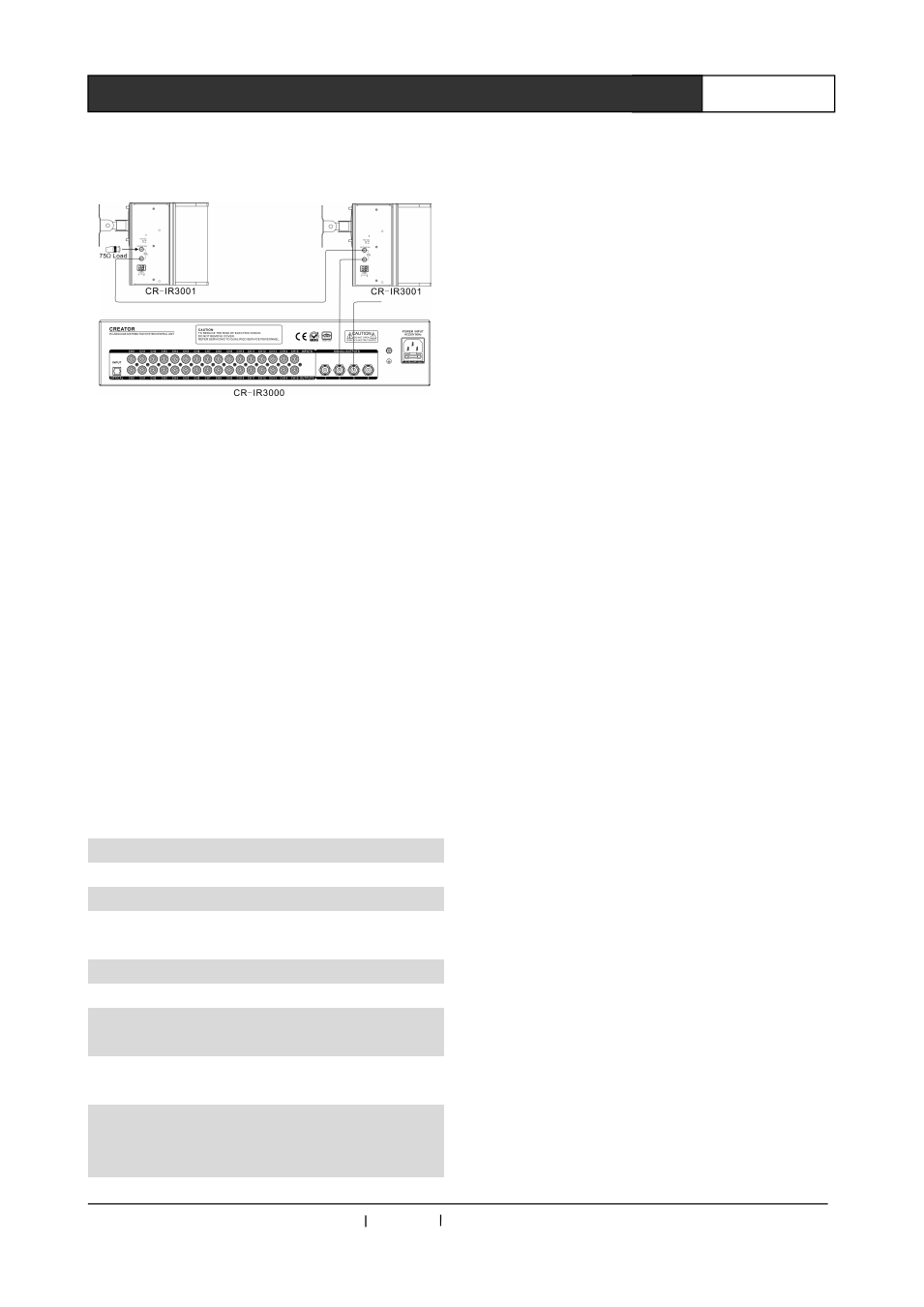
3.8 Connection between the radiating
panel and the controller
Attention: When cascading the radiating
panels, the BNC connector of the last panel in the
cascading chain which is left unused should be
connected to a load resistance of 75Ω in order to
match the impedance to avoid signal reflex.
3.9 Control and indication
◆
2 delay compensation button on the
transmitter to the radiation panel with different
cable
lengths
between
the
different
compensation.
3.10 Interconnection
◆
Output socket (2XBNC), used to connect the
transmitter and the next station radiation panel
cascading.
3.11 Physical features
Dimension
453(L)X230(W)X208(H)mm
Weight
About 7KG
Exterior
Gray Black
3.12 Electrical features
Power Supply
AC100-240V
Transmit power
36W
RF input
Impedance : 10kΩ , Margin :
100mV-3V
Maximum
cover
distance
76 meters
Automatically open
the switch threshold
voltage
100mV RF signal