3rectanglecoverage, 5installationstepsofradiatingpanels, 6delayswitchsettings – CREATOR Wireless IR Interpretation System User Manual
Page 20
CREATOR CORPORATION (CHINA) 2010-04 WWW.CREATOR1997.COM
13
Digital IR Language Distribution System User Manual
Fig. symmetrical connection (preferred)
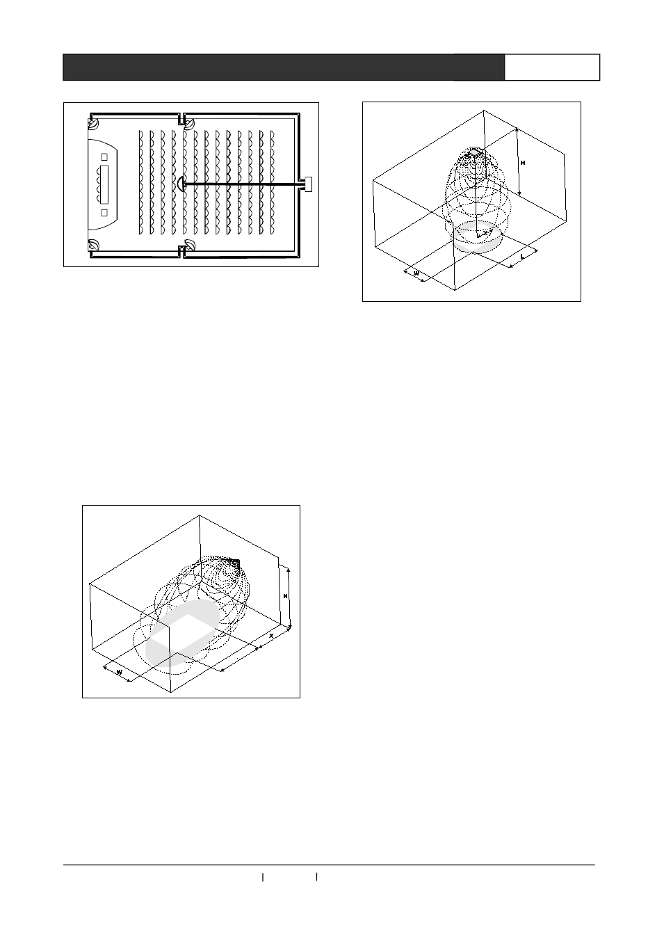
3.4.3 Rectangle Coverage
The actual required number of the radiating
panels can only be determined by field test, but
using “rectangle coverage” can ensure a very
close guess.
Fig.3-6 and Fig.3-7 explain what is the
“rectangle coverage”, from which we can see that
the rectangle coverage is smaller than the total
coverage. Notice: in Fig.3-7, “deviation value” X is
negative and the rectangle coverage is actually
bigger than the actual coverage.
Fig.3-6 15°installation: typical rectangle coverage
Fig. 3-7 90°installation’s typical rectangle
converage
3.5 Installation steps of radiating panels
◆
Take the instructions mentioned in section
1.4 to decide the positions of the IR radiating
panels
◆
Draw out the rectangle coverage in the layout
draft of the room
◆
If there are some areas which can receive
signal from two neighbor radiating panels, it
means that there is eclipsing effects. Draw out the
enlarged rectangle coverage in the layout draft.
◆
Check whether the radiating panels have full
coverage to certain spots; and if not, extra
radiating panels should be added.
3.6 Delay switch Settings
In section 1.4.6, there is “overlapping
multi-path effect”: the receiver receive signal from
two or more radiating panels, and “blind spots”
can be caused due to delay difference.
In order to compensate the delay difference,
the delay switch on the side of the radiating panel
can be set to increase the corresponding panel’s
delay. The LCD can display from 00 to 99, and the
digit is timed by 25ns, ie. The delay time can be
set is from 25ns to 2475ns (99*25).