3thesurfaceofthewalls,ceiling,floorand, 4thecoverageoftheradiatingpanel – CREATOR Wireless IR Interpretation System User Manual
Page 11
CREATOR CORPORATION (CHINA) 2010-04 WWW.CREATOR1997.COM
4
Digital IR Language Distribution System User Manual
1.4.3 The surface of the walls, ceiling, floor
and curtain
IR is just like visible light, and can be
reflected
by shining, smooth surface and
absorbed by dark, rough surface. The reflected
light generally can help by transmitting signals,
and won’t cause any damaging interference. In a
room with shining, smooth surfaces, the required
power of the radiating panel is lower than the
room with dark, rough surfaces, as curtain and
carpet.
Otherwise, the reflecting effect can be very
different when the texture of the floor is different:
the shadow of the walls and furniture can interfere
the IR transmitting. But if we use enough radiating
panels and allocate them properly, this problem
can be solved. At the same time, it should be
noticed
that
the
radiating
panels
cannot
positioned to face the windows without curtains,
which can reduce the radiating effect. As shown
in Fig. 1-7, there is difference in the reflection
effects for floors of different texture.
100%
100%
40%
80%
Fig. 1-7 there is difference in the reflection
effects for floors of different texture.
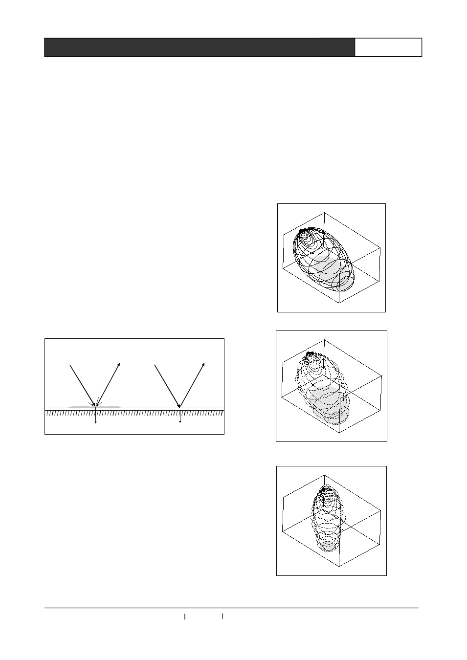
1.4.4 The coverage of the radiating panel
In the system, the coverage is decided by
radiating controller’s carrier wave and the
radiating panel’s output power, and the coverage
will be enlarged when there are more radiating
panels. The radiating panels’ total radiant
intensity is allocated in the controller according to
the amount of the carrier wave, and when the
used carrier wave increase, the coverage’s
percentage will decrease accordingly.
As shown in the following figure (the white
part),the
crossing
area
of
the
radiation
allocation area and the receiving area of the
people’s receiver is the coverage. Within the
coverage area, if the radiating signal can reach
the receiver directly, the intensity of the direct
signal can be enough to be received. Here the
following are some illustration figures for
installation for your reference:
15°installation figure
45°installation figure
90°installation figure