3cr-ir3001frontpanel, 4howtoallocationthesystem, 1theinstallationoftheradiatingpanel – CREATOR Wireless IR Interpretation System User Manual
Page 18
CREATOR CORPORATION (CHINA) 2010-04 WWW.CREATOR1997.COM
11
Digital IR Language Distribution System User Manual
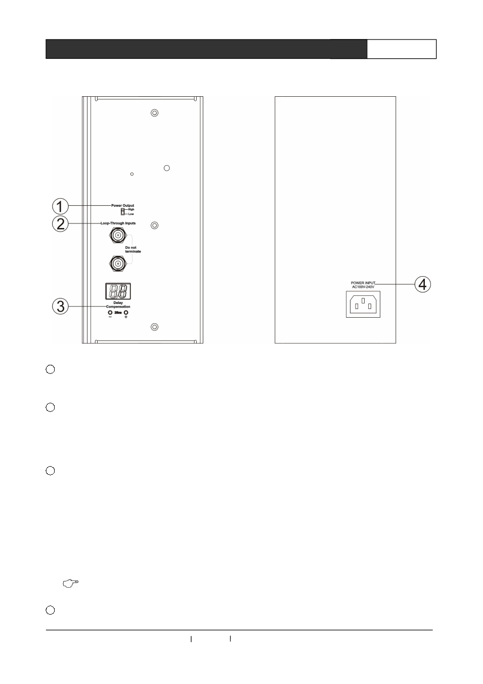
3.3 CR-IR 3001 Front Panel
1
POWER OUTPUT
Switch for the power of the radiated signal.
2
LOOP-THROUGH INPUTS
Connected
to
the
system
controller's
SINGNAL OUTPUTS interface or the former IR
radiating panel's output interface.
3
DELAY COMPENSATION*25
Delay composition adjusting button, “+” is to
delay increase, “-“ is to delay decrease. The
value for adjusting will be displayed on the LCD
above the button.
Delay composition range: 00~99, that is,
from 0(0*25)ns to 2475ns(99*25)
Cable delay coefficient:5.6ns/m,please refer
to the cable’s specifications for details.
3.6 “settings of the delay button”
4
Power input interface: AC100V~240V
50Hz/60Hz input
3.4 How to allocation the system
3.4.1 The installation of the radiating panel
The IR can reach the receiver by direct
reflection or diffused reflection. In a conference
hall, the delegates who sit behind others will not
receiver IR signal if it has been screened by the
front row of seats, which has to be taken into
consideration when allocating the radiating panel.
Thus, when the radiating panel should be
installed as high as possible, and generally the
height should be more than 2.5m and the
radiating
panels
should
face
the
whole
conference hall from various directions to make
sure their radiating area can cover the whole
place.
If the radiating panels are installed highly
enough, the signal intensity of the received IR
signal will not decreased to zero in the shadow