Comtech EF Data DST User Manual
Page 57
Digital Satellite Terminal System
Revision 1
Operation
MN/DST.IOM
5–5
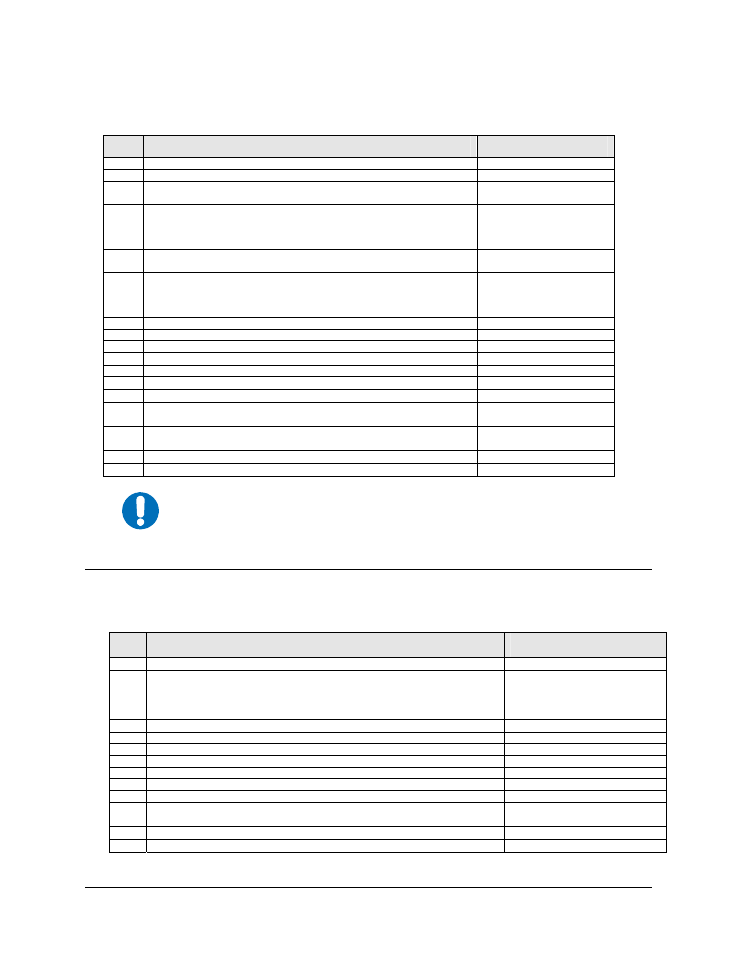
TX Side Setup:
Step
No.
Selection / Programming
Menu Location
13. Disconnect
BUC.
14.
Determine the ODU voltage required by the BUC and record for reference
15.
Turn the ODU Power = ON and Verify the BUC/ODU Voltage is correct.
The ODU voltage sent to the BUC is verified two ways per the next step.
Configuration: Modulator
16.
The ODU voltage is reported under the Monitor Menu.
To avoid damage to the BUC, confirm voltage matches the BUC voltage
requirement. (Typical Voltage is +24 or +48 VDC
± 5%)
Function Select: Monitor
For CEFD BUCs, refer to
Chapter 3, Table 3-1
17.
To protect the equipment, select the ODU Power = OFF. This is necessary
before connecting the L-Band coaxial cables to the unit
Configuration: Modulator
18.
Set the TX Terminal LO (MHz) and MIX (+ or -). The LO frequency is the
BUC local oscillator frequency and the MIX is.
Mix = “-” if the BUC LO > Satellite Frequency
Mix = “+” if the BUC LO < Satellite Frequency
Utility: Modulator
For CEFD BUCs, refer to
Chapter 3, Table 3-1
19.
Set Mod Spectrum to Normal or Invert.
Utility: Modulator
20.
Program the satellite frequency under the TX Terminal Frequency menu
Configuration: Modulator
21.
Set the TX Power Level to a safe (low) value
Configuration: Modulator
22.
Turn TX carrier to Off.
Configuration: Modulator
23.
Connect BUC.
24.
Turn TX reference to On.
Configuration: Modulator
25.
Turn TX ODU power to On.
Configuration: Modulator
26.
To automate warm up and delay carrier turn ON for a programmed delay
after prime power is applied see the ODU Output Delay menu.
Configuration: Modulator
27.
Record the nominal BUC current after the unit is warmed up and
functioning normally.
Function Select: Monitor
28.
Set the High alarm about 20% higher than nominal
Utility: Modulator
29.
Set the Low alarm about 20% to 40% lower for the ODU (BUC).
Utility: Modulator
IMPORTANT
At this point, the unit will start transmitting when the TX-IF output is tuned On
(under Configuration: Modulator menu).
5.4
Initial Operation of the Modem with the ODU and LNB
RX Side Setup:
Step
No.
Selection / Programming
Menu Location
30. Disconnect
LNB.
31.
Set the RX Terminal LO (MHz) and MIX (+ or -). The LO frequency is the BUC
local oscillator frequency and the MIX is.
Mix = “-” if the LNB LO > Satellite Frequency
Mix = “+” if the LNB LO < Satellite Frequency
Utility: Demodulator
For CEFD LNBs, refer to
Chapter 4, Table 4-1
32.
Set Demod Spectrum to Normal or Invert.
Utility: Demodulator
33.
Program the satellite frequency under the Rx Terminal Frequency menu
Configuration: Demodulator
34.
Select 10 MHz Ref = ON
Configuration: Demodulator
35.
Program LNB Voltage to the correct value (13, 18, or 24 VDC)
Configuration: Demodulator
36.
LNB Voltage OFF.
37. Connect
LNB.
38.
Program LNB Power = ON
Configuration: Demodulator
39.
Record the nominal ODU and LNB current after the units are warmed up and
functioning normally.
Function Select: Monitor
40.
Set the High alarm about 20% higher than nominal
Utility: Demodulator
41.
Set the Low alarm about 20% to 40% lower than nominal.
Utility: Demodulator