Adpcm audio (j6), Drop data input/send data (j7), Insert data output/receive data (j8) – Comtech EF Data UB-530 User Manual
Page 25: Drop data output (j9), 10 insert data input (j10), 6 adpcm audio (j6), 7 drop data input/send data (j7), 8 insert data output/receive data (j8), 9 drop data output (j9)
Breakout Panel
Revision 2
Connectors and Switches
MN/UB530.IOM
2–13
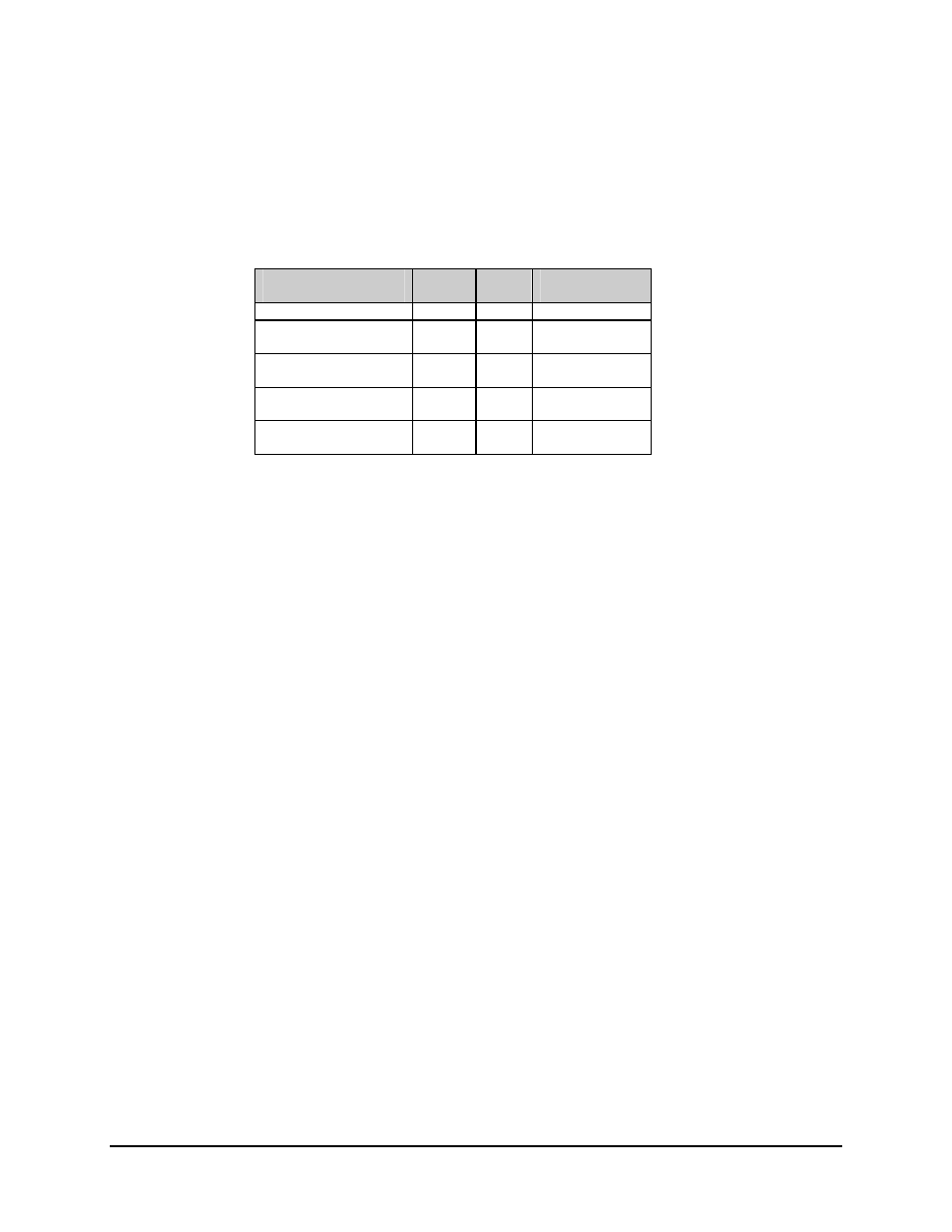
2.2.6 ADPCM Audio (J6)
The ADPCM audio connection is a 9-pin D connector located at the front of the breakout
panel. Screw locks are provided for mechanical security of the mating connector.
Audio
Signal Function
Name
Pin #
64k Data
(RS422)
Ground GND
3
Ground
ADPCM1 audio input
A1I–A
1
SDA (IN)
A1I–B
6
SDB
(IN)
ADPCM1 audio output
A1O–A
2
RTA (OUT)
A1O–B
7
RTB
(OUT)
ADPCM2 audio input
A2I–A
8
STA (OUT)
A2I–B
4
STB
(OUT)
ADPCM2 audio output
A2O–A
9
RDA (OUT)
A2O–B
5
RDB
(OUT)
2.2.7 Drop Data Input/Send Data (J7)
The connection for the unbalanced drop data input/send data interface is a BNC connector
located at the front of the breakout panel. For unbalanced operation, the configuration
switches on the rear of the panel must be set correctly (see Section 2.1).
2.2.8 Insert Data Output/Receive Data (J8)
The connection for the unbalanced insert data output/receive data interface is a BNC
connector located at the front of the breakout panel. For unbalanced operation, the
configuration switches on the rear of the panel must be set correctly (see Section 2.1).
2.2.9 Drop Data Output (J9)
The connection for the unbalanced drop data output interface is a BNC connector located at
the front of the breakout panel. For unbalanced operation, the configuration switches on the
rear of the panel must be set correctly (see Section 2.1).
2.2.10 Insert Data Input (J10)
The connection for the unbalanced insert data input interface is a BNC connector located at
the front of the breakout panel. For unbalanced operation, the configuration switches on the
rear of the panel must be set correctly (see Section 2.1).