Comtech EF Data CRS-170 User Manual
Page 20
CRS-170 1:1 Redundancy Switch
Revision 1
Installation and Operations Manual
MN/CRS170.IOM
22
2.4
Cabling with SDM-300L3 and SMS-301
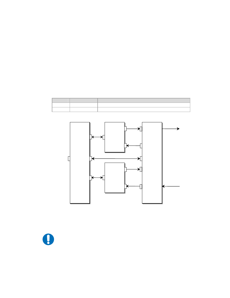
Figure 3 shows how to connect a pair of SDM-300L3 Modems together with the
SMS-301 and CRS-170 switches. The same configuration applies to SNM-1001L
and SNM-1010L.
The following table lists cable assemblies that may be supplied with the CRS-170
when used with the SDM-300L3 and SMS-301. The other cables between the
SMS-301 and the SDM-300L3 are the same cables supplied with the SMS-301 in
an SDM-300A application.
Quantity Part #
Description
1
CA/WR10163-1 SMS-301 to CRS-170 Control, DB15 Male to DB9 Male 4 ft
4
CA/6357-2
IF Coax Cable, 50Ω, length = 2 feet
Figure 3. Connection Diagram, SDM-300L3 and SMS-301
IMPORTANT
When connecting the Control cable between the CRS-170 and the SMS-301,
ensure that screw locks on the ‘D’ type connectors are securely fastened.
This will prevent the accidental un-mating of the cable, particularly when a
standby unit is being removed or replaced.
SDM -300L3
SDM -300L3
SDM -300L3
SDM -300L3
CRS -170
CRS -170
Tx
(Note 1)
Rx
(Note 2)
Tx
(Note 1)
Rx
(Note 2)
Notes:
1.
Includes Tx L -Band, BUC DC, 10 MHz and FSK
2.
Includes Rx L -Band, LNB DC, 10 MHz
Tx
L
-
Band
BUC DC
10 MHz
FSK
Rx
L
-
Band
LNB DC
10 MHz
User
Data
Interface
1:1 Control
SMS
-
301
SMS
-
301
Data
Data
J2 A
J3 B
J5
Tx A
J6
Tx B
J1
Rx A
J2
Rx B
J8
J7
J3 (Top)
J14
Modem A
Modem B
CP1
CP3
CP1
CP3
J8
J8
J1