Configuring the facility port, Connecting multiple lm-2s, Local inputs – Cloud Electronics LM-2B User Manual
Page 7
LM-2 Installation Guide v1.1
7
Configuring the Facility Port
The mic and line inputs on the LM-2 module will be available in the Zone as soon as the module is connected to the host unit’s
Facility Port for that Zone. The volume of the mic and line inputs will be determined solely by the level controls on the LM-2
faceplate and unaffected by any of the host unit’s front panel controls.
In order for the remote control section (background music source and level controls to operate correctly), the host unit must
be set for remote control operation.
Z4
MK3
and Z8
MK3
:
Set the
MUSIC CONTROL button on the host unit’s rear panel to REMOTE (in) for the Zone in use. The button is adjacent
to the REMOTE SOURCE + LEVEL connector immediately above the FACILITY PORT. This will disable the host unit’s front
panel music source and level controls for the Zone.
Sometimes it is desirable to permit remote control of music level but keep music source selectable only on the host unit. In this
case, internal jumper J1 on the sub-board for the Zone in use should be moved from ‘SW’ to ‘FR’. This will render the LM-2’s
music source switch inoperative, and return source selection to the front panel. See the Z4
MK3
/Z8
MK3
Installation and User
Guide for full details and jumper locations.
46-120 and 46-120
MEDIA
:
These units only have a single Facility Port, for Zone 1. Thus the LM-2 can only be installed in Zone 1. (If the LM-2 needs to be
added to a different Zone in an existing system, this restriction may be simply overcome by swapping outputs and renaming the
Zones.)
Set the two
REMOTE MUSIC CONTROL buttons (LEV and SRC) for ZONE 1 on the rear panel to REMOTE (in). The
buttons are immediately below the 4 x 3-pin REMOTE CONTROL PANEL CONNECTORS. This will disable the host unit’s
front panel music source and level controls for Zone 1.
Sometimes it is desirable to permit remote control of music level but keep music source selectable only on the host unit. In
this case, set the
SRC button for ZONE 1 back to FRONT PANEL (out). This will render the LM-2’s music source switch
inoperative, and return source selection to the front panel. See the 46-120/46-120
MEDIA’
s Installation and User Guide for full
details and jumper locations.
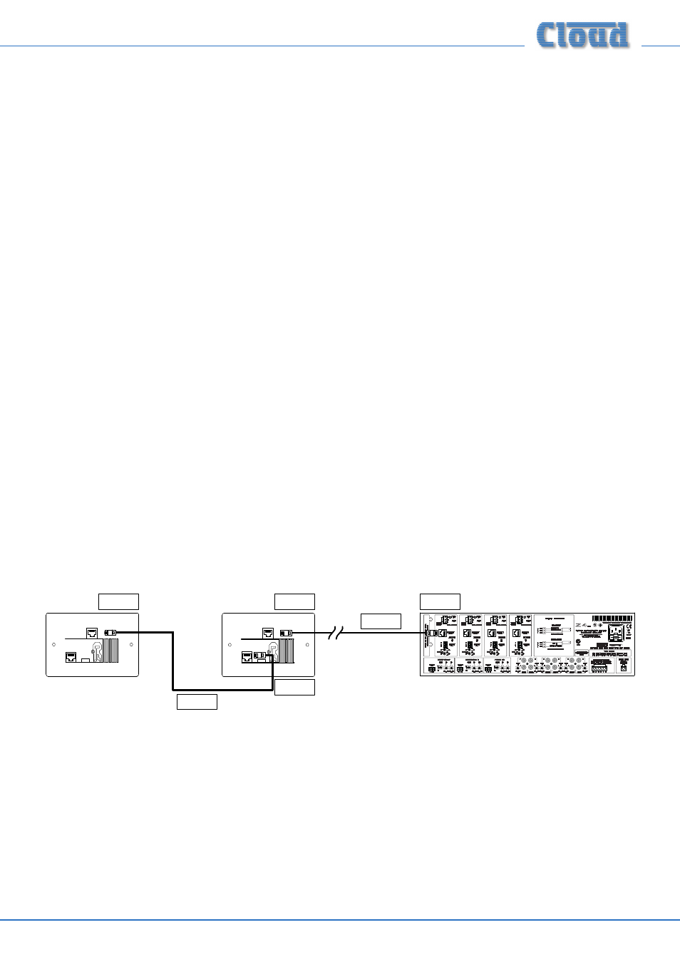
Connecting multiple LM-2s
Two or more LM-2s may be installed in the same Zone by employing the LINK connector on the lower rear PCB. The primary
purpose of this feature is so that microphones and music sources may be connected into the audio system at different locations
within a single Zone (typically one of large area or complex layout).
LINK
LINK
OUTPUT
OUTPUT
LM-2
(UK version illustrated)
Connect to
OUTPUT socket
Connect to
OUTPUT socket
Connect to
FACILITY PORT
Screened
Cat 5 cable
Screened
Cat 5 cable
Connect to
LINK socket
Local inputs
When modules are “daisy-chained” together in this way, the audio signals from each module are summed together to produce
a single mono feed to the host unit. Thus two (or more) microphones may be connected within a zone and either or both used
as wished, with individual mic level controls at their respective modules.
An internal gating circuit on each module automatically “disconnects” any chained modules which are not in use, to minimise
noise contribution. Should this the gate function not be required for any reason, it may be disabled by linking two solder pads
on the lower PCB - see page 8. (Remove the lower PCB from the faceplate before attempting to make this link.)