Cloud Electronics LM-2B User Manual
Page 6
LM-2 Installation Guide v1.1
6
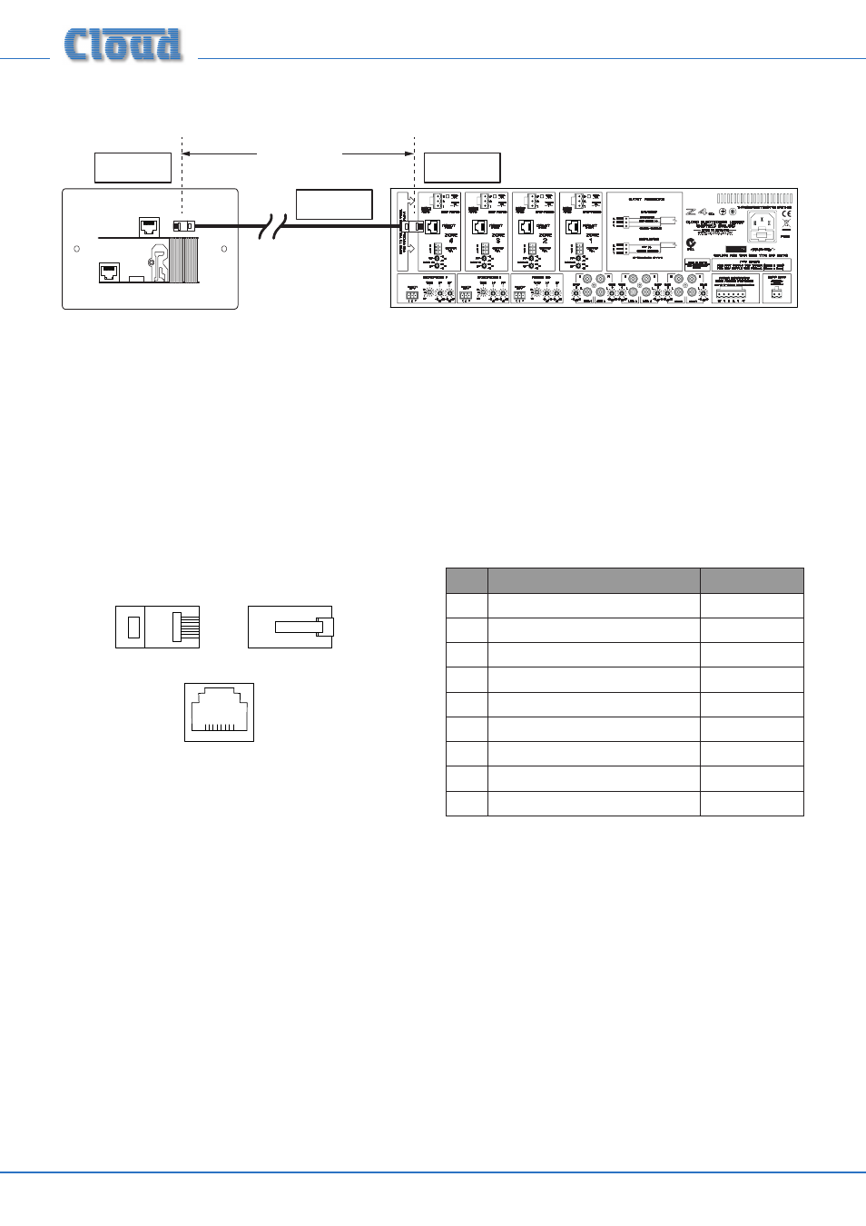
The LM-2’s OUTPUT connector should be connected to the host unit’s FACILITY PORT for the Zone in which it is installed*
with screened Cat 5 cable and shielded RJ45 plugs.
LINK
OUTPUT
LM-2
(UK version illustrated)
100 m max
Connect to
OUTPUT socket
Connect to
FACILITY PORT
Screened
Cat 5 cable
The maximum total Cat 5 cable length should not exceed 100 m. If further modules are being “linked” together (see below),
this figure applies to the overall cable run from the host unit to the “furthest” module in the chain.
IMPORTANT: Because the cables carry low-level audio, only screened Cat 5 should be used, the foil screen of the cable being
bonded to the metal screening can of the plugs. If an LM-2 is being installed in very close proximity to the host unit, it may be
possible to use ready-made screened Cat 5 “patch” cables of short length. In all other situations, shielded RJ45 plugs should be
crimped onto the installed screened Cat 5 cable using the pinout shown below.
PIN
USE
Cat 5 CORE
1
Audio ‘cold’ phase (-)
White + Orange
2
Audio ‘hot’ phase (+)
Orange
3
Priority VCA control
White + Green
4
+15 V
Blue
5
0 V
White + Blue
6
-15 V
Green
7
Music level control (0 to 10 V)
White + Brown
8
Music source select control (0 to 10 V)
Brown
SCN
Screen for system music controls
Connector shell
* There is no reason why the module cannot be connected to the Facility Port of a Zone other than that in which it is installed – though this is likely to be an
unusual installation scenario.