Block diagram, Installation - connections – Cloud Electronics LM-2B User Manual
Page 5
LM-2 Installation Guide v1.1
5
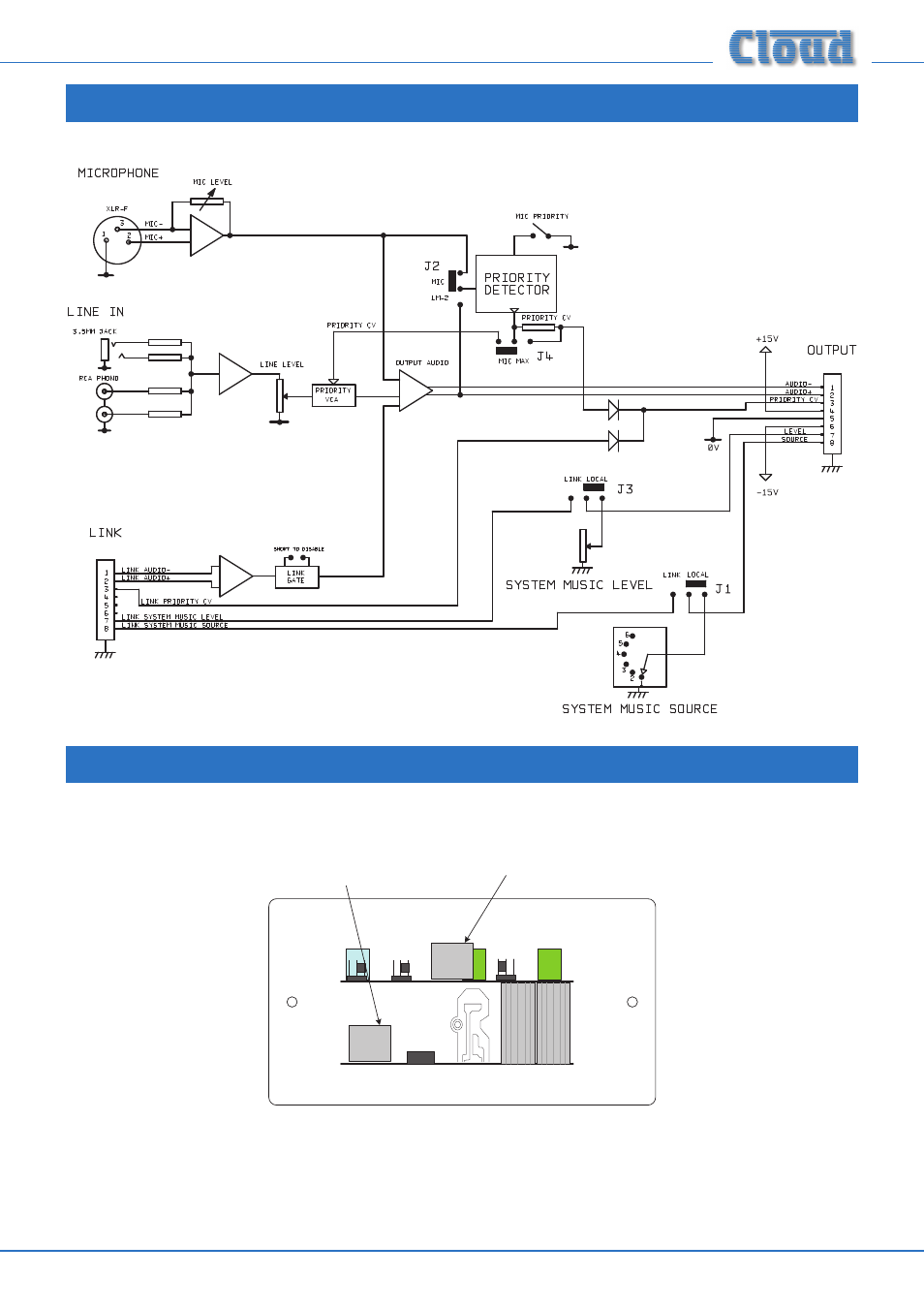
Block Diagram
RJ45
RJ45
Installation - connections
The LM-2 has two PCBs mounted on the rear of the faceplate. The OUTPUT RJ45 connector is located on the upper PCB while
the LINK RJ45 connector is on the lower:
OUTPUT
LINK
(Sketch simplified; only primary components shown)
LOCATION OF REAR RJ45 CONNECTORS
This manual is related to the following products: