1 electrical cable connection, 1 video interface, Figure 2-2 cable connections for the video port – Broadata Communications 272E Series User Manual
Page 7
BCI 272E User’s Manual
Digital Fiber Optic Video/Audio/Data Transport System
Broadata Technical Support, (800) 214-0222
8
2.2.1 Electrical Cable Connection
The three available cable connections on the electrical side are
for video, audio and data connections. Follow the proceeding
instructions in order to properly install your electrical
connections.
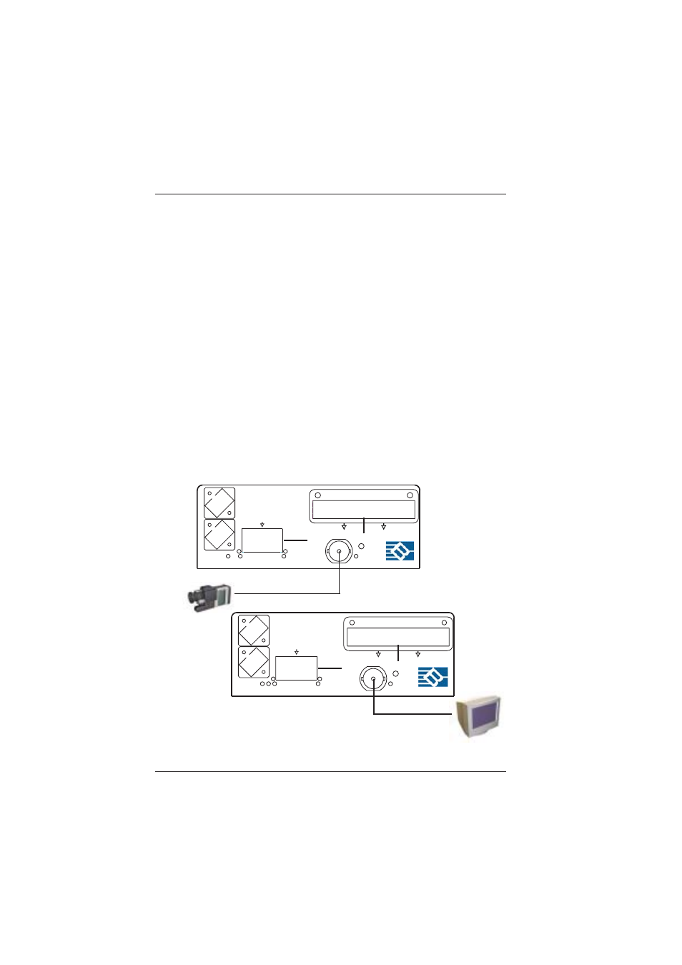
2.2.1.1 Video Interface
The 272E is capable of receiving and transmitting one baseband
video signal unidirectionally. The video signals are connected
through an video cable (e.g., RG59U). Use the following
procedure for installing video devices.
For the near-end TX unit, connect and label one video cable to
the user’s video source connector labeled “VIDEO OUTPUT”
(e.g., camera) and connect the other end of the cable to the
272E “VIDEO” connector. (See Figure 2-2).
Figure 2-2
Cable Connections for the Video Port
RX
--
+ --
+
--
+
--
+
O
-
-
I
+ --
+
D-OUT
PWR
A-IN
D-IN
A-OUT
DATA
RR
R
IN
L
L
VIDEO
L
L
R
AUDIO
271/272E-T
DATA
TX
OUT
DATA
+
271/272E-R
I
+ --
PWR
RX
A-IN
LINK
D-IN
TX
--
+
-
+ -- + --
+
--
O
-
VIDEO
IN
D-OUT
A-OUT
DATA
L
R
R
L
OUT
AUDIO