0 setup – Broadata Communications 272E Series User Manual
Page 6
BCI 272E User’s Manual
Digital Fiber Optic Video/Audio/Data Transport System
Broadata Technical Support, [email protected]
7
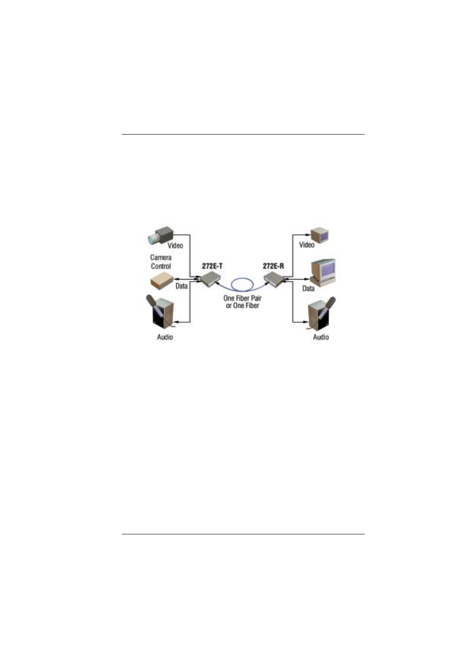
2.0 SETUP
The BCI 272E Series units are used in pairs. One 272E-T transmitter
unit is located at the near-end and connected through one optical fiber,
to the 272E-R receiver located at the far-end of the link. Figure 2-1
depicts a typical installation for the 272E-T/R.
Figure 2-2
272E Setup
2.1 Mounting
Before installing the units into your housing, make sure there is
enough space to pull and connect both the electrical and optical
cables without stressing them beyond the manufacturer’s
limitations (also known as the minimum bend radius).
2.2 Cabling and Connectors
In order to setup the BCI 272E properly, make sure to observe
the following instructions when installing the proper cables. The
272E requires two parts to the cabling setup: the electrical and
the optical.