12 parallel interface lpt – BECKHOFF CB4051 User Manual
Page 31
Parallel Interface LPT
Chapter: Connectors
Beckhoff New Automation Technology CB4051
page 31
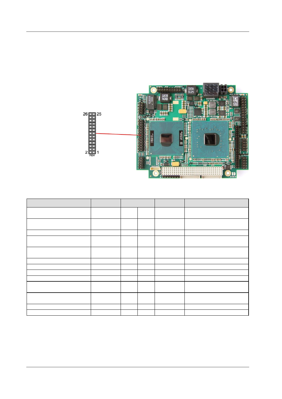
4.12 Parallel Interface LPT
The parallel interface is a standard IDC socket connector with a spacing of 2.54 mm. The port address
and the interrupt are set via the BIOS setup.
The parallel port may be selected in BIOS-setup to interface to a standard PC floppy drive, but a special
cable is required for such operation. Please contact your sales representative for such a cable.
Pinout LPT interface (FDC signals in brackets):
Description
Name
Pin
Name
Description
strobe
STB#
1
2
AFD#
(DRVDEN0)
automatic line feed (drive
density 0)
LPT data 0 (Index)
PD0 (IDX#) 3
4
ERR#
(HDSL#)
error (head select)
LPT data 1 (track 0)
PD1 (TR0#) 5
6
INIT# (DIR#) init (direction)
LPT data 2 (write protect)
PD2
(WPRT#)
7
8
SLIN#
(STP#)
select input (step)
LPT data 3 (read data)
PD3
(RDATA#)
9
10
GND
ground
LPT data 4 (disk change)
PD4 (DC#)
11
12
GND
ground
LPT data 5
PD5
13
14
GND
ground
LPT data 6 (motor 0)
PD6 (MT0#) 15
16
GND
ground
LPT data 7 (drive select 0)
PD7 (DR0#) 17
18
GND
ground
acknowledge (drive select 1) ACK#
(DR1#)
19
20
GND
ground
busy (motor 1)
BUSY
(MT1#)
21
22
GND
ground
paper end (write data)
PE (WD#)
23
24
GND
ground
select printer (write enable)
SLCT (WG#) 25
26
VCC
5 volt supply